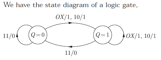
Q. 31 A state diagram of a logic gate which exhibits a delay in the output is shown in
the figure, where X is the don’t care condition, and Q is the output representing
the state.
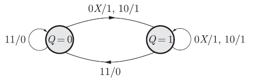
The logic gate represented by the state diagram is
(A) XOR
(B) OR
(C) AND
(D) NAND
Answer:(D)
Explanation:


Excellent