Q. 23 The circuit shown in the figure is used to charge the capacitor C alternately from two current sources as indicated. The switches S1 and S2 are mechanically coupled and connected as follows:
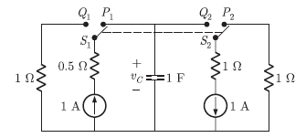 Assume that the capacitor has zero initial charge. Given that u(t) is a unit step function , the voltage
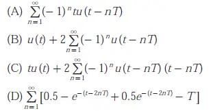
 ![]() across the capacitor is given by
across the capacitor is given by
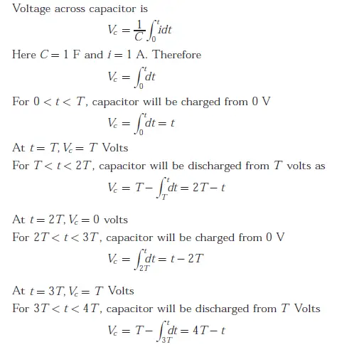
Answer: C
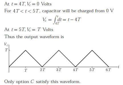
Explanation:


