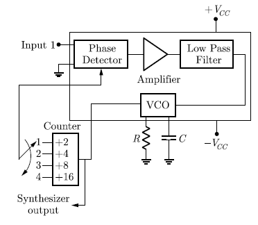
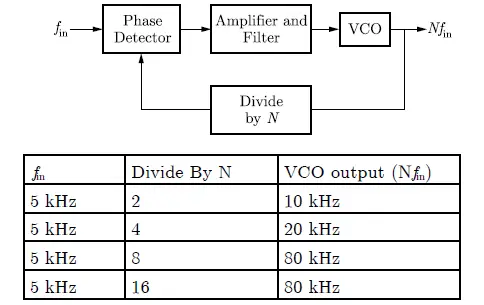
Q.26 The block diagram of a frequency synthesizer consisting of Phase Locked Loop (PLL) and a divideby- N counter (comprising ÷2, ÷4, ÷8, ÷16 outputs) is sketched below. The synthesizer is excited with a 5 kHz signal (Input 1). The free-running frequency of the PLL is set to 20 kHz. Assume that the commutator switch makes contacts repeatedly in the order 1-2-3-4.
The corresponding frequencies synthesized are:
(A) 10 kHz, 20 kHz, 40 kHz, 80 kHz
(B) 20 kHz, 40 kHz, 80 kHz, 160 kHz
(C) 80 kHz, 40 kHz, 20 kHz, 10 kHz
(D) 160 kHz, 80 kHz, 40 kHz, 20 kHz
Answer: (A)
Explanation:


