Power Factor Improvement Reactive Power Compensation:
Power Factor is nothing but the ratio of real power to apparent power. It is unit less quantity. Sometime for sinusoidal wave the power factor is defined as the cosine of angle between voltage and current.
In this article we are going to see entire study about power factor.
[wp_ad_camp_2]
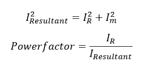
Also generally induction load consists of two current one is load current or real current and another one is reactive current. Real current (IR) use to drive the motor and reactive current (Im) is used to magnetize the coil. Also power factor can be defined as the ratio of true current to resultant current. Here resultant current and Power factor can be calculated as follow
Disadvantage of low power factor:
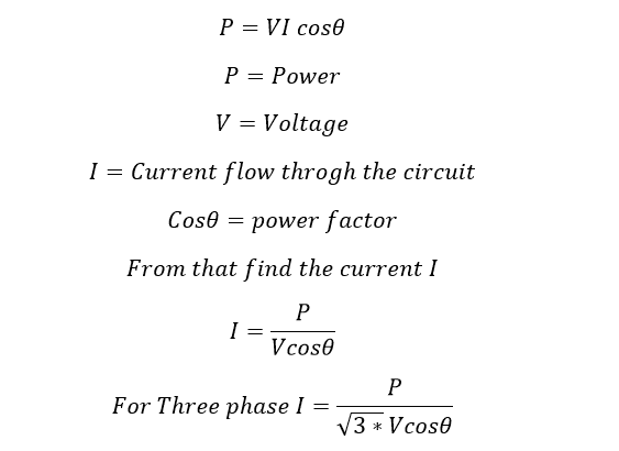
Power factor plays important role of an electrical Power system. i.e consider a single phase power system. The power flow in the network will be
From that you can say that the Load current will be increase as the power factor decreases for fixed power and voltage. Poor power factor causes the following disadvantages.
- Increases the line copper loss, finally we get poor transmission efficiency
- Increases the size of the conductor as the line current increase. Here the cost is inversely proportional to the square of the power factor. Hence poor power factor causes high capital cost.
- Large KVA rating of equipment-larger size and expensive: All electrical equipments in connection with generation, transmission distribution of ac power such as alternators, transformer, switchgear, cables etc are rated on KVA basis.
The larger the power factor, the larger is the KVA rating. Therefore, at low power factor, the KVA rating of the equipment has to be made more, making the equipment larger and expensive.
Also see:
- Relationship of Frequency Vs KVA Output or Rating of Transformer
- What is Circuit Breaker & Rating of Circuit Breaker
- Why DC Does Not Have Power Factor ?
- Leading Power Factor And Lagging Power Factor
- Poor Voltage regulation: The large current at low lagging power factor causes greater voltage drops it electrical equipments. Therefore, at receiving end we have face heavy voltage drop. To keep the voltage drop we have to install additional equipment such as Voltage regulator.
- Loss of generating capacity The lagging power factor reduces the handling capacity of all the elements of the system. It is because the reactive component of current prevents to full utilization of installed capacity.
Reason for Low Power Factor:
- In Most of the industry, we will use three phase induction motor. Normally, the induction motor power factor will be 0.3 to 0.5 during light load condition and during full load condition the power factor increases to 0.85 to 0.95.
- Using High number of arc lamps, electric discharge lamps and induction furnaces. All are operating at low power factor typically 0.1 to 0.3. They are extremely low.
- During light load condition, the voltage range become high, which increases the magnetizing current. This results poor power factor.
Avoid Low Power Factor:
- We can choose three phase synchronous motor instead of Induction motor.
- Using High Speed Induction Motor instead of Low Speed Induction motor because, Low speed induction motor has poor Power factor.
- Loading the induction motor above 90%.
- Reducing the air gap in the motor, by installing ball bearing and roller bearing instead sleeve bearing. Air gap causes increasing the magnetizing current
See: How to Read & identify Bearing Number
Economics of Power Factor Improvement:
The industrial energy consumption bills are based on two parts. One is energy consumed by the load and another one is based on demand that drawn from the system. Here the energy consumed by the load does not affect by the low power factor but the demand drawn from the source increases as the power factor decreases. Let see.
The demand is a counting of KVA consumption. Typically, it is called maximum demand. Maximum demand is defined as the maximum power drawn from the system at the instant. It is a KVA quantity. Here KVA is
[wp_ad_camp_2]
As the power factor decreases the KVA also increase. Hence the bill amount also increases. So that improving power factor is good for our system as well as consumer. Let see the method of improving power factor.
Methods of Power Factor Improvement:
The low power factor occurs due to the inductive loads. But we use almost 95% of the inductive loads such as motors, induction stove, electromagnet etc. These are loads are leads to poor power factor at final. Here some of the equipments are used to neutralize the lagging component. Which means we cannot reduce the reactive power instead if we can supply reactive power to the load by installing the below mentioned equipments. Let see the power factor improvement component.
- Static Capacitor
- Synchronous motor
- Synchronous condenser
- Phase advancer
- Synchronous-induction motor
- Use of High speed motor.
Power factor Improvement using Static capacitor:
As you know capacitor is a fundamental source of reactive power or capacitor delivers the reactive power to the electric network. These capacitor panels are called APFC panel which means automatic power factor controller. The static capacitors are connected in parallel with the load terminal either star connection or delta connection. But Mostly star connections are preferred. However, you can make four different type of connection of capacitor.
Also See:
- Why Battery Cannot Store AC voltage
- Why Capacitor and Inductor are used in Filtering Circuit
- Why capacitor is required for Single phase motor
- Why Capacitors Use As High Voltage Protection
- What is Capacitance, Capacitor Series and Parallel Connection
- Star connection
- Delta connection
- Series connection
- Shunt connection
Advantage:
- Less losses
- Less maintenance
- Very easy Installation
Disadvantage:
- Life span is less typically four or six years from the date of installation.
- Easily damaged when the voltage exceeds the rated.
- Use and through, we cannot re-use the same capacitor.
Power Factor Improvement Using Synchronous Motors:
Generally synchronous motor power factor can be improved by adjusting field excitation of the synchronous motor. by maintain the power factor at 1 or – 0.8 which decrease the reactive power drawn from the source. Hence the system power factor improved.
Power Factor Improvement Using Synchronous Condenser:
An over excited synchronous motor running on no load is called as synchronous condenser or synchronous phase advancer. It is behaving live capacitor, and the motor generate reactive power and it supplies to the grid or system.
Advantage:
- Fine control can be obtained
- Fault can be removed
- Overloading is possible for shorter time.
Disadvantage:
- High cost as compared with capacitors
- Create heavy Short circuit current when the faults occur near the synchronous condenser
- High nosily.
Power Factor Improvement Using Phase Advancers:
It is an another source of reactive power. Phase advancer is nothing but a AC exciter which is connected on the main shaft of the motor and operates with the motor’s rotor circuit for power factor improvement. It is a simple principle of magnetizing the stator through rotor. The excitation current will be feed in to the rotor circuit, at slip frequency. Therefore, the power factor of induction motor will be improved. This process is called Phase advancer.
Shunt and series type of phase advancer are available according to the excitation winding of the phase advancer.
Advantage:
- The reactive power drawn from the source get reduced
- The phase advancer can be installed wherever the synchronous motors are not allowed.
Disadvantage:
- It can be used only up to 150 KW motor.
Location of these Power factor correction Equipment installation:
- Synchronous condensers are used at load centers and Transmission system receiving end.
- Static Capacitor can be installed where ever you want to improve the power factor. Installation process is very easy
Significance of Power Factor Improvement: Key points
- Load Current can be reduced as reducing the magnetizing current
- Voltage level can be increased
- Loss can be reduced
- Reduction of KVA loading of the generator
- Reduction in the KVA demand as it results reduce the electricity cost
Also see:
- Control Circuit Control Supply Power Circuit Power Supply Definition
- Distribution Transformer & Power Transformer
- Droop CT – Droop Current Transformer
- Harmonic In Electrical | How Electrical Harmonics Occurs in Power system
- How VFD Saves Power & Basic Concept of VFD
- Low Forward Power Protection 32F
- Reverse Power Protection Working Principle -32R
- What is Neutral Why Neutral is required in Single Phase Power Distribution
- Why Earthing Transformer are used
- Why in India 11kV, 22kV, 33kV, 66kV, 132kV…
- Why India has 50 Hz Power System and US has 60 Hz 110 Volts Power System
- Why Tertiary Winding is used in transformer?
- Why transformer Rating in KVA exact answer
- Why VFD Duty Motor Frame Size is Higher Than Normal Motor


