Alternating current:
The circuit’s conventional current varies in a repetitive manner, such circuit is called alternating current circuits. The electron flow changes its direction positive to negative and negative to positive. Alternating current is generally called as AC, hence a circuit with alternating current is known as AC circuit. The source, which produces the alternating current to the circuit can be called as AC source. An alternating current changes its direction periodically. The periodic changes are called as frequency.
Example: Dynamo, Home electricity, all high-frequency waves, transformer output and input voltage,
[wp_ad_camp_1]
Note: Transformer cannot be operated with DC supply.
History:
Hippolyte Pixii built the first alternator in 1835 in Paris, France, a device which utilized a magnet rotated by a hand crank to produce AC (alternating current). Scientists at the time were more interested in DC (direct current), but once the advantages of AC power were realized, it became the world standard for electricity.
Note: Alternating current generation is nothing but a converting mechanical energy into electrical energy
Best Example for Alternating Current Generation or production:
Consider a dynamo in your younger age, you might be seen dynamo, which is the best example for the alternating current generation. Let start how dynamo generates Alternating current
Alternating current generator Dynamo parts:
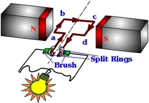
It has one rotating part which is called a rotor, and another is the stationary part which is called stator. The dynamo’s stator, which has two poles, N and S. Both poles are made off with natural magnets. here the rotor (rotating part). Normally dynamo is called as permanent magnet generator. It cannot be called as the alternator. The main difference between the alternator and generator is.
Alternator => field is rotating where armature is standing. (Field circuit as Rotor and Armature circuit as the stator), Example: 3 Phase alternator.
Also see: Why We should give DC supply to field circuit.
Generator => Armature is the rotating field is standing. (Field circuit as stator and Armature circuit as the rotor) Example: Dynamo, DC Generator, AC exciter.
Rotating Part of a Dynamo:
Rotating part of a copper wound Coil in the plate, which has ABCD four corner, two carbon brushes X, & Y which is used to bring the output of the dynamo to the outside, prime mover which is used to drive dynamo’s rotor. Carbon brushes are designed to touch the generator output terminal and the brushes are connected with spring contact to avoid loose contact between two surfaces (brush and generator). But always there is some voltage drop occurs in the brushes appx. 0.5 to 1 % of the generating voltage. The surface of the brush contact is made of smooth and easy to slip during the rotation. The current density (electric current per unit area of cross-section.) is depending upon the type of materials are used to construct the carbon brushes. Read more.[wp_ad_camp_1]
Working Function:
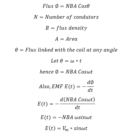
As we know from Faraday’s law or electromagnetic induction, in simple Words When the moving conductor is kept in a magnetic field, which produces EMF is the circuit, the EMF is directly proportionate to the Strength of the magnetic field. Or Faraday’s law is stating that when the magnetic flux linking a circuit changes, an electromotive force is induced in the circuit proportional to the rate of change of the flux linkage. The Direction of the current can be known from the Fleming right-hand rule.
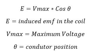
Here “E” is an English letter used to denote the induced emf Unit of induced emf in volts
Step1:
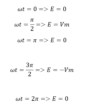
Let us assume that the coil is rotating in the clockwise direction with the angular velocity omega, when the conductor A B C D is in horizontal position AB in left side and CD in the right side (the conductor is kept in the direction of the flux, then no flux cutting, no emf hence induced emf is equal to zero.
Step2:
Then move the same conductor by 90 deg in the clockwise direction where the conductor starts cutting the magnetic flux. Simultaneously the emf start induces… here the conductor AB in top position and CD in down position, the conductor cuts the maximum number of flux, which leads to reaching the high induced emf in the conductor’s coil.
Step3:
Again move the conductor by 90 deg clockwise (at the same time induced emf starts decreasing) then the conductor is in the parallel with the flux direction here there is no flux cutting induced emf is equal to zero. Here AB in the right side position and CD in the left side position. Here we get one complete half cycle by rotating a conductor by 180 from its original position.
Step4:
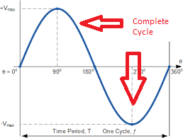
Again Move the conductor by 90 deg clockwise direction. During this rotation, the induced emf start increasing negative direction. The conductor cuts maximum flux hence the induced emf also is high. Here the AB in down side and CD in the top side. Conductor cuts maximum Flux hence the induced emf reaches maximum voltage in negative. Also here the current changes its direction.
[wp_ad_camp_1]
Let see why current reverse in the negative direction:
The generating EMF is
Here conductor reaches 270 deg angle,
because the cosine of 90 + angle gives negative Value, due to this reason, we get the negative value of the induced EMF.
Step5:
Again, in the same way, move the conductor by 90 deg, here we get the induced emf start decreasing (mathematically increasing) from –Emax to zero. The conductor reaches in parallel with the flux direction, here no flux cutting hence the induced EMF in the conductor is zero. This the first position, the process repeats to generate steady emf.
If the flux linked with the coil at an angle theta
When the coil in the same direction of the magnetic field…
[wp_ad_camp_1]
Hence the Alternating current has the nature of sinusoidal wave structure.
Output:
In practical Alternating Current Generation:
Alternator: A device that generates alternating current from a source of rotating motion (mechanical energy to electrical energy), such as a turbine powered by flowing water or steam or a windmill. Alternators work by using the rotating motion to spin a magnet that’s placed within a coil of wire. As the magnet rotates, its magnetic field moves, which induces an alternating current in the coiled wire.
Motor: The opposite of an alternator. It converts alternating current to rotating motion (electrical energy to mechanical energy). In its simplest form, a motor is simply an alternator that’s connected backward. A magnet is mounted on a shaft that can rotate; the magnet is placed within the turns of a coil of wire.
When alternating current is applied to the coil, the rising and falling magnetic field created by the current causes the magnet to spin, which turns the shaft.
Transformer: Consists of two coils of wire placed within close proximity. If an alternating current is placed on one of the coils, the collapsing and expanding magnetic field will induce an alternating current in the other coil.







![What is Arc Chute? Types, Working Principle [Video Included] arc chute working priciple](https://www.electrical4u.net/wp-content/uploads/2020/06/arc-chute-218x150.png)