What is Voltage Drop:
Voltage drop, in the word itself, it means itself, here the drop is nothing but a loss and it says the loss in the voltage or reduction in the voltage is called voltage drop.
Why is voltage drop important in the electrical system?
Yes, due to the voltage drop, the power supply to the circuit get reduced, resulting lights to flicker or burn dimly, heaters to heat poorly, equipment damage, improper working, less output, less efficiency, loss of money by paying excessive electricity bill, motors to run hotter than normal, speed drop, small motors do not start and changes to burn out.[wp_ad_camp_1]
How voltage drop arise?
There are many reasons for voltage drop.
- Internal resistance (Direct Current) or impedance (Alternating Current) of the source (internal resistance blocks the flow of electron or charges)
- Conductor’s resistance (including resistivity, cross section of the conductor and length of the conductor)
- Across contacts, and across connectors
- Loss contact
Easy to understand about Voltage drop:
Simple and easy understand about voltage drop is garden hose pipe. Consider Voltage as the water pressure supplied to the hose pipe and Current (flow of electron or charges) as water flowing through the hose pipe. And the internal resistance of the hosepipe is determined by the type and size of the hose – same as electrical conductor’s length, MOC (Material of construction) and size.
Must Refer: What is the difference between resistor and resistance
Allowable Voltage Drops:
The National Electrical Code recommends the voltage drop should not be exceeded more than 3 % from the source to utility. Example if you have a circuit voltage of 240 AC and you have a one light at 100 meter long. You have planned to give power supply to the lights, here the supply at the light terminal should receive 233 Volts and the drop should not exceed 7.2 Volts.
Standard utility allowable voltage drop:
For 480 volts Power system the output of the transformer secondary side should be a minimum of 480 volts and 430 V should be at utility end.
Also see:
- Why in India 11kV, 22kV, 33kV, 66kV, 132kV…
- Why India has 50 Hz Power System and US has 60 Hz 110 Volts Power System
Note: The changes in the transformer’s incoming, the output voltage also reduce.
For 240 volts Power system the output of the transformer secondary side should be a minimum of 240 volts and 200 V should be at utility end.
For 120 volts circuit system the output of the transformer secondary side should be a minimum of 120 volts and 110 V should be at utility end.
The voltage drop permissible limit in India:
Maximum allowable voltage drop in India in various area
| Part of Distribution System | Urban Area (%) | Suburban Area (%) | Rural Area (%) |
| Up to Transformer | 2.5 | 2,5 | 2.5 |
| Up to Service Main | 3 | 2 | 0.0 |
| Up to Service Drop | 0.5 | 0.5 | 0.5 |
| Total | 6.0 | 5.0 | 3.0 |
Voltage variations in 33 kV and 11kV feeders should not exceed the following limits at the farthest end under peak load conditions and normal system operation regime.
- Above 33kV (-) 12.5% to (+) 10%.
- Up to 33kV (-) 9.0% to (+) 6.0%.
- Low voltage (-) 6.0% to (+) 6.0%
The same range cannot be maintained in rural area, because rural area has many interconnections, power to be transferred for long distance, and power theft etc. In these cases, 11/0.433 kV rather than the usual 11/0.4 kV distribution transformers can be used.
Fair use Ref: Energypedia article
Voltage Drop Calculation For DC (direct current) power system:
In DC power system, we can calculate voltage drop across the conductor by using basic ohm’s law formula. Also, using Kirchhoff’s circuit laws (Voltage and current) You can find, the sum of the voltage drops across each component of the circuit is equal to the supply voltage.
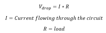
The resistance of the conductor can be calculated by using the mathematical expression of given conductor’s size, length of the conductor, cross-section of the conductor, and Material conductor made up off.
Note: inductor act as a short circuit for Direct Current.
Voltage Drop Calculation for AC (Alternating Current) power system:
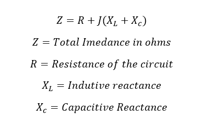
Consider a conductor which carries alternating current, two elements are perfectly doing this action. One is resistance and another one is reactance. In an Ac power system the opposition to the current flow occurs because of resistance and reactance typically it is called impedance. Here, the vector sum of oppositions to current flow from both resistance and reactance is called impedance. Here impedance is denoted by variable Z. SI unit of Impedance is Ohm.
[wp_ad_camp_1]
The total impedance of the circuit is depending upon the frequency of the Alternating current and magnetic permeability. The Voltage drop in AC circuit can be calculated from Ohm’s Law.
![]()
Case Study Regarding Voltage drop:
I had worked in a power plant and we had an issue whenever we start 250HP Motor (three phase, 440V and 50 Hz), the plant light starts flickering. Also, the lighting distribution feeder (MLDB) was installed in the same panel. We had planned to rectify that issue. We measured the feeder voltage when the motor starts rotating. At that time, we saw that the feeder voltage drops from 440 V to 380 volts for 7 sec. So we identified The feeder voltage dropped from 440 Volt to 380V, due to that, we had an issue with the lighting system. To correct that problem, we changed the incoming supply of the lighting circuits. The issue permanently solved. Created separate feeder for all lighting circuits…or use separate lighting transformer.
See here: What is the purpose of Lighting Transformer
MLDB: Main Lighting Distribution Board.
Also see:
- Why induction motor Takes high starting current
- Why Inductors Use In Filtering Circuit and VFDs
- Why is Battery United AmpsHour AH
- What is Reactive Power
- What is Busbar Current Carrying Capacity Calculation 5 Types of Busbar
- What is Capacitance, Capacitor Series and Parallel Connection
- What is Capacitor Basic Concept Of Capacitor
- What is Circuit Breaker & Rating of Circuit Breaker
- What is Conductance
- What is Conventional Current and Electron Current
- Why Star delta starters are preferred for higher HP motor
- Why Tertiary Winding is used in transformer?
- Why transformer Rating in KVA exact answer


 Conversion Calculator DC, 1 Phase, 3 Phase")
 Calculator DC, Single Phase & Three phase")
 Electrical Unit?")
