Power circuit:
Power circuit is nothing but, distribution of power to the motor through a certain equipment like MCCB/MPCB/SFU, contactor, protection relay, Power cable, Connector etc. The size of the equipment will be varied according to the load circuit. (size of the motor, heater etc.) while designing this power circuit you must calculate all power parameters (supply voltage and load current) which means when increasing the supply voltage, you need to increase the insulation level of the power cable and size of the conductor and when increasing the load capacity, you need to increase the size of the cable.
MCCB/MPCB/SFU/SDF
It will isolate the power circuit during abnormal condition. Click this
Also see: What is MCB, How to select MCB and How to Avoid Failure of MCB
Contactor:
This is the main power control unit. In which the mechanical contact converts into electrical contact when the contactor’s coil energize through control circuit. It consists of coil, fixed contact, Moving contact, arc shoot and Contactor base.
Never Forget to see:
Contactor base: It is used to mount whole contactor unit into the panel or feeder. All mechanical moving mechanism is placed in this circuit (coil, fixed contact, moving contact)
Fixed contact: The contact surface area or contact area is depending upon the contactor size.
Moving Contact: It is a moving part of the contactor. It gives the mechanical contact with the fixed contact. When the contactor energized the fixed and moving contact touch together and there is the path to the flow of current, then the motor or any power circuit start running.
The life time of the both contact tip is depending upon the number of operation and breaking current capacity. Frequent short circuit / higher load during motor stall condition may damage the contact tips very sooner. You need to clean them at least once in 3 months. While finding on the tips damage or insufficient contact you must need to replace them both. While doing maintenance you should use CRC (Carbon Retra Chloride), CTC (Carbon Tetra Chloride), rubber to clean carbon particle. You do not use any smoothening materials like any type of emery paper, which will damage the coating on the tips. The coating will extend the life time of the both contact.
Lack of maintenance leads to single phasing on the three phase motor during running condition (Motor Failure)
Needs Frequent maintenance: frequent on/off operation hoist, long trolley, cross trolley, centrifugal machines etc.
Arc shoot: It is used to quenching the arc while contactor opening or closing time.
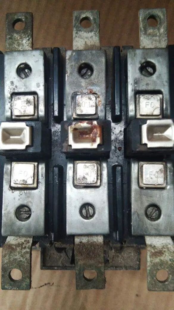
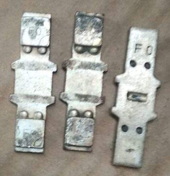
Spreader link:
All cables cannot be connected in the power contactor terminal. So that the contactor manufacturers are giving spreader links to connect the power cable with contactor. While purchasing big size contactor do not forget to purchase spreader links
For example: If you are using Siemens make 3 TF 57 contactor Star/ delta starter (320KW,540 amps) For this you need 2 Run X 2 side motor terminal (X,Y,Z= X’,Y’,Z’)= 4 cable of 300 Sqmm cable. 2 run 300 Sqmm Cable cannot be connected directly to the contactor terminal. By using this spreader link you can connect easily.
Nerver Forget to see: How to calculate cable Size
Protection Relays:
The Protection relay units are the master mind of the circuit. It protects the whole unit from any fault condition. The relay units are varied according to the principle of operation. It just opens the contact (which associate with the fault) or cut the supply going to the contactor’s coil or gives trip command to the circuit breaker. Some relays are here (mainly used in industry)
- Thermal over load relays
- Numerical relays
- Electromagnetic type relays, etc…
Cables:
It provides interconnection or looping between the all other equipment. The size of the cable varied according to the voltage level and current carrying capacity. It consists of two parts. Here you can find the cable size and its current carrying capacity.
- Core
- Insulation
Core: It carries the current to the destination point. The material of construction will be of Copper, Aluminum, Silver, gold, iron etc.
Also see: How to Avoid Cable Failure
Cost effect: Gold > Silver > Copper > Aluminium > iron
Effect of usage: Aluminium > Copper > Silver > Gold (rarely used)
Effect of losses: The cable losses or Voltage drop are purely depending upon the resistivity of the material.
| Material | Resistivity ρ (ohm m) | |
| Silver | 1.59 | x10-8 |
| Copper | 1.68 | x10-8 |
| Copper Annealed | 1.72 | x10-8 |
| Aluminum | 2.65 | x10-8 |
| Iron | 9.71 | x10-8 |
Iron > Aluminium > Copper > Silver > Gold
Insulation: This is the filling material or layered material in between the two different surfaces is called insulation. In industry two types of electrical insulation are mainly used
- PVC (Poly Vinyl Chloride)
- XLPE (Cross Linked Poly Ethylene)
Where to use:
PVC insulation will withstand upto 120 Deg. Celsius. It is suitable for Underground cabling applications.
XLPE insulation will withstand up to 160 Deg. Celsius. It is suitable for Overhead cabling applications.
According to the stand used:
- Single stand
Upto 10 Sqmm size will be manufactured.
- Multi stand
Reduce skin effect and Flexible usage. Any size can be manufactured.
What is meant by skin effect:
The electron will flow on the surface of the conductor is called skin effect.
Connector: It is used to connect indoor circuit to outdoor circuit.
Why connectors are required:
In order to reduce the damage of main feeder material like Contactor, thermal overload relays.
Example: if you are connecting power cable directly with the contactor or thermal overload relay, due to the loose contact (if any), the temperature will rise at that terminal and there is a chance of damage in the contactor/thermal over load relays. To avoid this, you can connect the power cable through connector with the contactor. The connector cost is less as compare to the contactor cost.
Thanking You!!!!!
Also See:
- Basic Concept of VFD
- VFD Control Drawing
- Why Induction Motor Takes Higher Starting Current
- Basic Electrical Explanation
- Fundamantal Electrical Definition
- Electrical and Electronic components Table
- Electrical & electronic symbols
- Electrical & electronic units
- Electronic circuit laws


