What is Electric Circuit and Electronic Circuit:
An electric circuit is a path in which electrons from a voltage or current source flow. Which should contain active and passive components.
Source:
The point where those electrons enter an electrical circuit is called the “source” of electrons. Electron always try to reach source point with load (control loads such as heater, motor, electrical fan etc) or without load (short circuit, earth fault etc). The point where the electrons leave an electrical circuit is called the “return” or “earth ground”. The exit point is called the “return” because electrons always end up at the source when they complete the path of an electrical circuit.
[wp_ad_camp_1]
Note: Electron’s starting Source terminal and returning source terminal should not be in same polarity. i.e if electrons start from negative terminal then the returning terminal should be positive terminal. If you connect the same terminal (negative with negative), then you cannot get the current flow (charge)
Load:
Electrical Load can be derived as a part of an electrical circuit Where in between (source to return) the circuit current path or between the electrons’ starting point and the point where they return to the source. Example electrical heater. In electrical heater the electron starts from positive terminal and it pass through a heater and reaches negative terminal of the source. Finally, you will get the output as heat energy.
Note: Load always Consumes Electrical energy.
Example: A load of an electrical circuit as we are well-known home appliances such as electrical fan, refrigerators, televisions, or lamps or more.
How to Identify electrical and electronic circuits:
Both Electrical and electronic circuits can be complicated. Both circuit’s components and their connections are plotted by a drawing. To read an electrical or electronics drawing needs some special skill. Before reading any drawing you must have the electrical or electronics component’s symbol. Making a drawing of the connections to all the component parts in the circuit makes it easier to understand how circuit components are connected each other.
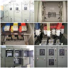
Electric Circuit Example:
Drawing in an electronics circuit is called circuit diagram. In physically, to complete electronic circuit connection soldering guns or a special type of machines are used.
In the same way, the drawing in an electrical circuit is called wiring diagram. In physically to connect, electrical circuit components mostly flexible cables are used. Before starting work on any wiring connection you should make necessary safety precaution. Because of electrical wiring diagram is generally performed in 220 Volts or 110 volts. A small wrong connection will lead to heavy short circuit.
Both electrical and electronic diagrams are usually drawn by draftsmen and then printed. Diagrams may also be created digitally using specialized software.
Wiring and circuit diagrams utilize special symbols recognized by everyone who uses the drawings. The symbols on the drawings show how components like resistors, capacitors, insulators, motors, outlet boxes, lights, switches, and other electrical and electronic components are connected together. The diagrams help to commission the circuit working properly or not.
A schematic is a diagram of an electrical circuit. Schematics are graphical representations of the essential connections in a circuit, but they are not life-like depictions of a circuit. Schematics use symbols to represent components in the circuit.
Electronic Circuit:
Electronic circuits usually use low voltage direct current sources such as 5V, 12 V or 24 Volts and 110Volts are commonly used in a circuit. 5 Volts are used in microprocessor, 12 volts are used in resistor and 24 Volts are used in electronics relay circuit, 110Volts are used in electrical wiring diagram such as circuit breaker wiring, protection relay wiring, other electromechanical relays etc. Electrical circuit always preferred to wiring with DC supply why?
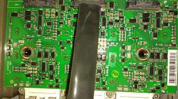
Electronic Circuit Example:
[wp_ad_camp_1]
Another best example: Your Smart Phone
A load of an electronic circuit may be as simple as a few resistors, capacitors, and a lamp, all connected together to create the flash in a camera. Or an electronic circuit can be complicated, connecting thousands of resistors, capacitors, and transistors. It may be an integrated circuit such as the microprocessor in a computer. Electronics circuits are playing major role in this digital world.


 Conversion Calculator DC, 1 Phase, 3 Phase")
 Calculator DC, Single Phase & Three phase")
 Electrical Unit?")
