DC GENERATOR
In day to day life we cross many common terms such as DC generators, motors etc. this devices are called as DC machines. Either converts electrical energy into mechanical or mechanical energy into electrical energy.
The device which converts mechanical energy into direct type electrical energy is called DC generator. The device which converts electrical energy into mechanical energy is called as DC motor.
Here we are going to see only DC generator.
The DC generator working principle is whenever the conductor cuts the magnetic flux lines an emf is induced it which generates the sinusoidal current.
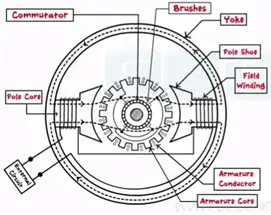
Construction of DC machine
DC machine made up of two main parts static parts and rotating parts
Static parts are yoke, poles, and brushes. Rotating parts are armature, commutator and bearings.
Yoke
The yoke is the outer frame of the DC machine. It is made up of magnetic material called cast iron.
Pole
Every machine has even number of poles divided into three parts pole core, pole shoes, field winding.
Armature
It is cylindrical in shape and it is mounted on circular shaft. Armature is a part of a machine which rotates in a circular direction.
Commutator
It is a cylindrical body mounted on a shaft along with the armature thus forming a single body. Hence the commutator is rotates along with the armature.
Brushes
The brushes are made up of carbon and mounted on the commutator and they are stationary and do not rotate. The external load circuity is connected across these brushes.
Bearing
The main function of the bearing is to support the rotating part and allow its smooth motion with the minimum friction.
Working principle
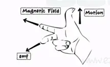
Dc generator works on faradays laws of electromagnetic induction it states that when the conductor cuts the magnetic flux lines an emf is induced in it. This induced emf is stated from the Fleming’s right hand rule.
For DC generators we sue Fleming’s right hand rule as we need to find out the current.
For DC motors we use Fleming’s left hand rule as we need to find out the motion.
Fleming’s right rule states three fingers thumb, index finger and middle finger are outsourced so that they are mutually perpendicular to each other. Index finger is made to point the direction of magnetic field thumb indicates the direction of motion of conductor middle finger indicates the direction of emf induced in the conductor.
The induced emf given by the equation
e=Blvsin (ɵ) units in volts
e= induced emf
B= flux density in wb/m²
l= length of conductor (meter)
ɵ = angle between the direction of the motion of the conductor and magnetic field.
Construction of DC generator
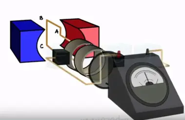
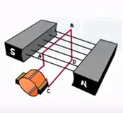
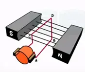
DC generator is constructed by keeping two conductors AB and CD between to magnets both these conductors are connected to the commutators and the brushes one mounted on the surface of these commutators which the external circuit is connected.
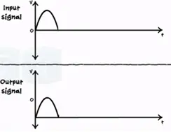
Whenever the conductors cut the magnetic flux lines the emf is induced that causes the current flow through the load circuit when conductor reaches vertical position and rotating in clock wise direction. We get the maximum current continuous motion reaches its 180° position current becomes ‘0’ momentary.
ɵ = Blvsin ɵ
Emax = Bmax, Bmax= 0 momentary
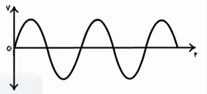
This 0° to 180° rotation we get the positive half of the AC current generated.
When AB attains the vertical value at 270°
We get the maximum current again the process generates continuous AC current.
During the positive half conductor AB touches the brushes B1. Thus B1 attain the positive charge during the positive cycle at the output. When AB touches the brush B2, B2 attains the positive charge and providing positive cycle gain.
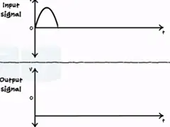
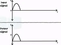
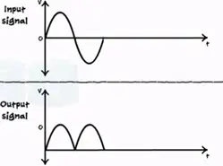
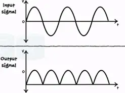
The commutator are so designed for every cycle current will flow out towards the circuit given positive output only.
The emf equation for the DC generator is given by
Eg = PɸN/60 * Z/A
P = number of poles of generator
ɸ = flux produced by each pole in weber (wb)
N = speed of diameter in rpm
Z = total number of armature conductors
A = number of parallel paths in which the total number of conductors are divided.
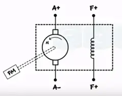
The symbolic representation of DC generator
DC generators are divided into two types
- Separately excited
- Self-excited
Separately excited DC generator
Separately excited DC generator the field winding is supplied from external separate DC supply.
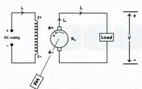
PM – prime mover N- Speed of armature in rpm Es – emf induced in armature
Rs – Armature resistance If – armature current V – Terminal voltage I˪ – load current
The EMF induced given by the equation
Eg = V + IaRa + Vbrush + Armature reaction drop.
Self-excited DC generator
The field winding is connected parallel with the armature as the load increases armature current increases. Thus voltage drop IaRa increases as result load voltage decreases.
Self-excited DC generator is further divided into three types they are
- Shut generator
- Series generator
- Compound generator
Application
- Battery charging
- Ordinary lightning
- Power supply purpose


