CATHODE RAY OSCILLOSCOPE
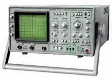
Every single electric circuit multiple components connected to each other. At every point we have test the circuit with the help of some parameters like voltage, current dissipated power etc. we also study the wave forms of parameters to decide a working of circuit very common used electronic equipment this CRO. It is widely used measuring instrument in laboratories and industries.
Block diagram of CRO
It is made up of different blocks; they are vertical amplifier, delay line, trigger circuit, time base, horizontal amplifier, CRT
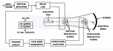
Vertical Amplifire
Input signal is displayed on the CRO is applied to vertical amplifier. This amplifies the weak signals that produce the measurable deflection on the screen. The vertical amplifier decides the sensitivity and bandwidth of the CRO, its output is given to input of delay line.
Delay Line
We know input signal applied to horizontal and vertical deflection plate but before reacting horizontal deflection plate signal passes through different blocks such as trigger circuit, time base generator, horizontal amplifier. Thus small delay occurs and signal reaches the vertical deflection plates before the horizontal plate. This causes the distortion signal on the screen.
To avoid this situation a small amount of delay is added in the line block after the vertical amplifier.
Trigger circuit
This circuit generates the trigger pulses keep synchronous between the input signal and horizontal deflection circuit.
Time base generator
Time base generator produces saw tooth waveform and applies in horizontal deflection plates. As saw tooth waves varies linearly with time. The movement of spot of screen takes place at constant velocity. Hence x-axis of CRO calibrated in terms of time and input displayed with respect to time.
Horizontal amplifier
The strength of saw tooth signal available on output of time base generator is not sufficient thus before applying it to horizontal plates. The signal is amplified using horizontal amplifier.
Power supply
Every instrument needs a power supply to work. Power supply section of CRO generates two levels of DC volt.
LVT- used for working of electronic circuits
HVT- used for anode of CRT. HVT generates in order to 1000 volts to 1500 volts
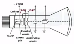
CRT
Entire CRT is enclosed in a evacuated glass tube. It consists of three main parts they are
- Electron Gun Assembly
- Deflection plates
- Phosphor screen
Electron gun assembly
The V-from that we see in diagram nothing but a ray electron generated by electron gun assembly. Electron gun assembly consists of heater, cathode, control grid, accelerating anodes, focusing anodes.
Cathode is indirectly heated to emit electrons. These electrons are passed through centre grid centre grid has centrally located hole co-axial with axis tube. Negative voltage is applied to the grid. Negative charge repels electrons and generates narrow beam. By controlling charge negative voltage applied to the control grid we can control the intensity of the beam. This electron beam is passed to the accelerating and focusing anodes. The anodes are supplied with high positive voltage and increase the velocity of beam and keep the beam focussed. By controlling the positive voltage applied at anodes the focus of the beam can be controlled.
Deflection plates
The focus beam with very high velocity is passed through X and Y deflection plates. These are horizontal deflection plates and vertical deflection plates. The forces on the both plates controlled by waveforms as shown
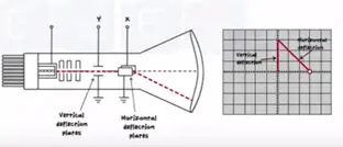
Phosphor screen
The focus accelerated and deflected beam are made to strike inside part of the CRO screen with very high velocity. Inner side of the screen is coated with special type of phosphor. This layer converts electrical energy into light energy. Whenever an electron strikes the screen with high velocity it generates bright spot on the screen. The beam moves so fast and appears on the waveform.
Measurement of voltage and frequency of waveform
To measure voltage and frequency we have two knobs on the front panel of CRO volts/div and time/div.
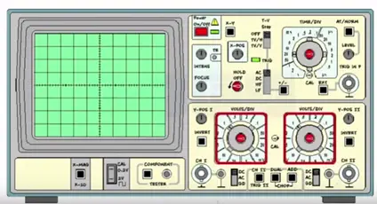
Measurement of voltage
Whenever the waveform is displayed of CRO voltage is measured as a peak voltage scaled on the Y axis.
The following procedure to be followed while measuring voltage
Count number of division in vertical direction in Y axis which corresponds to peak value.
Let’s assume four divisions
Note the position of volt/div knob and keep volt /div= 1. Calculate peak to peak voltage as follows.
Peak to peak voltage= no of division * volts/ division value
4*1= 4 volts
This peak to peak volt = 4 volts


