What is Servomotor:
Servomotor, in that word itself we get full functional explanation. Servomotor=Servo+Motor. Here, servo means closed loop. Hence, Closed loop + Motor is equal to servomotor. A closed loop motor is called servomotor.
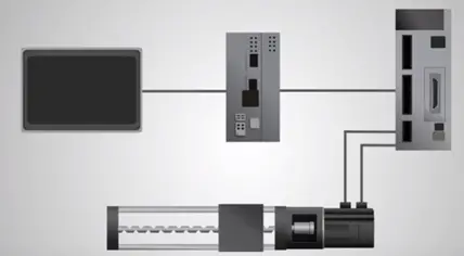
It is a part of closed loop system and comprised with several parts namely control circuit, servomotor, shaft, amplifier, either encoder or resolver. Servomotor is a self-controlled electrical device that rotates a machine with high efficiency and with great precision. The output shaft of the motor moved at particular angle, position and velocity and regular motor does not have.
Servomotor is a regular DC motor (AC Motor For Some Special Application such as CNC Machine, Industrial automation) and couples it with a sensor for positional feedback. The controller is the most important part of the motor designed and used specifically for this purpose, servomotor is closed loop mechanism that incorporates position, and feedback already controlled the rotational speed position. The meter is controlled with the electrical signal either analog or digital which determines the amount of movement which represents the final command position for the shaft.
The type of encoder serves as the sensor providing the speed and position feedback. This circuit is built the right inside the motor housing which is usually feed with the system.
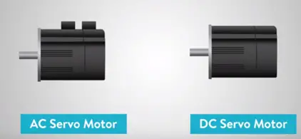
Types of servomotor are classified into different types.
- AC servomotor
- DC servomotor
There are three main considerations to evaluate servomotor,
- Based on the current type AC or DC
- Types of commutation used brushed or brush-less
- Motors rotating field synchronous or Asynchronous
AC or DC
The AC or DC consideration is the basic classification of the motor. Based on the type of current used, Looking at the performance stand point the primary difference between AC or DC motors inherit ability to control the speed. With the DC motor speed is directly proportional to the supply voltage with constant load and in AC motor speed is determined by the frequency of the applied voltage in the number of magnetic poles. Both AC and DC motor used in servo systems AC withstand higher current with commonly used in servo application such as robots, inline manufacturing and other industrial applications with high reputation and high precision.
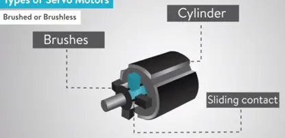
Brushed or Brush-less
DC servomotor is committed mechanically with brush using commutator or electronically without brushes. Brush motors are generally less expensive simple to operate, brush-less is more reliable having higher efficiency and less noisy.
A commutator is a rotary electrical switch periodically reverse the current direction between the rotor and drive circuit it consists of cylinder compost of motor for metal contact called brushes of a soft conductive material such as carbon press against the commutator making a sliding contact with segments of the commutator as it rotates.
The majority of the motors used in servo systems AC brushes less design and brush permanent magnet DC motors or sometimes employed servomotors for simplicity and low cost.
The most common type of brushed DC motor in servo application is the permanent magnet DC motor. Brush-less DC motor replaces the physical brushes and commutator with electronic means of achieving commutation typically with the Hall Effect sensors or encoders.
AC motors are generally brush-less or other some designs such as the universal motor which can run either AC or DC power. They do have brushes and mechanically commutated.
Synchronous or Asynchronous
DC motors are generally categorized brush or brush-less. AC motors are differentiated by speed of the rotating synchronous or Asynchronous field.
If we call as AC or DC consideration than in a AC motor speed is determined by frequency of the supply voltage and number of magnetic poles. This speed is referred to synchronous speed. Therefore synchronous motor rotates at the same speed as the stator rotating magnetic field.
In Asynchronous motor normally referred as an induction motor rotor rotates speed is lower than the stator is rotating magnetic field. The speed of the Asynchronous motor can be varied by utilized by several control method such as change in number of poles and change in frequency.
Working principle of DC servomotor
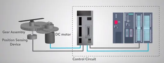
Dc servomotor is constructed with four major components DC motor, position sensing device, gear assembly, control circuit. The desired speed of the DC motor is based on the voltage applied. In order to control the motor speed potentiometer produces a voltage which is applied one of the inputs to error amplifier. In some circuits control panels is used to produce DC reference voltage corresponding to desired position or speed of the motor and its applied to the pulse with voltage converter. The length of the pulse decides the voltage applied to the error amplifier as a desired voltage to produce the desired speed or position for the digital control PLC or any other devices.
The feedback sensor is normally potentiometer they produce voltage corresponding to absolute angle of the motor shaft through gear mechanism. Feedback voltage value is applied at the input error comparator amplifier compares the voltage generated from the current position of the motor resulting from the potentiometer feedback and desired position of the motor reducing an error either an positive or negative voltage. This error voltage applied to the armature of the motor as the error increases the output voltage applied to the armature as long as error exists. The comparator amplifier amplifies the error voltage and corresponding power the armature. The motor fill the error comes zero. If the error negatives the armature voltage removes and hence the armature voltage reverses and armature rotates in the opposite direction.
Working principle of AC servomotor
The AC servomotor is based on the construction with two distinct types of AC servomotor they are synchronous and Asynchronous or induction motor.
Synchronous motor
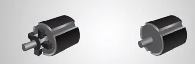
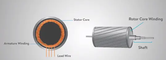
Synchronous motor consists of stator and rotor. Stator consists of cylindrical frame and stator core armature coil wound around the stator core and core is connected to a lead wire through which current is provided to the motor.
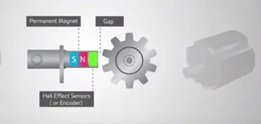
Rotor consists of a permanent magnet is referred with the Asynchronous induction type rotor and in the current in the rotor is induced by a electro magnetism and therefore these types are called brush-less servomotor.
When the stator field is excited with voltage rotor follows the rotating magnetic field of the stator at the same speed or synchronous with the excited field. With this type of permanent magnet rotor number rotor current is required, so the stator field de-energies and stops rotor also stops. These rotors have higher efficiency due to absence of rotor current, when the position of rotor with respect to stator is required and encoder is placed on the rotor and provides the feedback to servomotor controller.
Asynchronous or Induction motor
Induction motor consists of stator core, armature winding, lead wire and rotor consists of shaft, rotor core winding most induction motor contain the rotational element the rotor or squirrel gauge only the stator is fed around the stator winding with AC supply.
The alternating flux field revolves with synchronous speed, the resolving flux is called the rotating magnetic field or RMF. The volatile speed between the stator rotating magnetic field and rotor conducts induced magnetic force in the rotor conduction according to Faraday’s law electromagnetic induction. This is the same action occurs in the transformer. The induced current in the rotor also producing alternating flux field around itself this rotor flux lags behind the stator flux.
The rotor velocity related between in the rotating stator flux filed in the rotor rotates same direction as that of stator flux. The stator is not succeeding catching after the flux speed or not synchronized hence the type Asynchronous is derived.


Keep in touch