What is Standby Earth Fault Relay:
A Standby earth fault relay is nothing but an earth fault protection used to protect the generator, transformer, and motor from the external earth fault (earth fault outside the zone. for example grid side earth fault).
As you know in electrical power system, the fault occurs due to various factors such as natural disturbance, lightning on the transmission line, falling trees on the transmission lines, animal fall on the insulator, insulation failure, cable failure, electrical equipment failure, etc.
In such fault is classified into two categories on is a symmetrical fault (L-L-L-G) and another one is an unsymmetrical fault (L-G, L-L, L-L-G, L-L-L, and L-L-L-G).
In this, one of the relays is used to protect our system against L-G, L-L-G, L-L-L-G faults. The relay is called the Standby Earth fault relay.
It is used to protect the system if the neutral current or unbalance current reaches the predetermined value, then the standby earth fault relay operates.
Why it is called standby earth fault relay?
It is backup protection for restricted earth fault (REF) relay. It operates the CB when REF is failed to trip the circuit, Heavy earth fault outside of the REF protective Zone, and all other earth faults. Simply we can say, it is standby protection for all other earth faults.
Standby Earth fault Relay Construction:
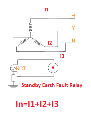
In Neutral side, one current transformer will be installed at a neutral side of the transformer or alternator.
The current reference will be taken from the neutral CT. On the panel side, and over a current element will be directly connected with the CT reference.
Look at the image below, here the noted NCT is used only for stand by earth fault protection.
Note:
To get better operating performance from the Standby earth fault relay, we should provide a current reference to the relay from individual CT or separate core output (if we use multi-core CT). The CT reference should not be shared with any other equipment.
For alternators, we should install the current transformer separately. But power transformer or distribution transformer comes with NCT (Neutral current transformer). We can take the current reference from the NCT.
Note: If you do not use the NCT output, then the CT secondary should be in short condition.
Standby Earth fault Relay Working Function:
Consider the Current in the three phases are I1, I2, and I3 the natural current is IN. During Normal condition, there is zero current flow in the neutral.
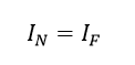
Apply Kirchhoff’s current law,
I1 + I2 + I3 = IN = 0
The relay does not operate the trip circuit associated with the relay.
During the abnormal conditions, for example, there is a fault in phase R, hence the unbalance fault current goes to the Neutral.
The current transformer reads the unbalance fault current and if the fault current exceeds the preset value, the relay operates.
Note: In practical, always some amount of current flows in the Neutral typically 1-15 Amps depending upon the rating of the equipment i.e for 25MW alternator IN= 10 -15 amps at full load. Because all the phases are exactly equal in magnitude and phase.
What happens if the standby earth fault relay operates?
The standby earth fault protection creates a class A trip. Hence, Relay 51N operates, Master trip relay 96 operates, and the circuit breaker 52 trips.
Note that A simple overcurrent relay can be used as standby earth fault protection.


 and No Voltage Relay Working Principle")


