Merz Price Differential Protection for Transformer:
Merz price differential protection is used to protect the transformer from internal short circuit, Internal ground faults and inter turn shorts. Transformer is a static device. Merz price differential protection is nothing but a percentage differential protection Which works under the principle of circulating current scheme.
Merz Price Differential Protection Working Principle:
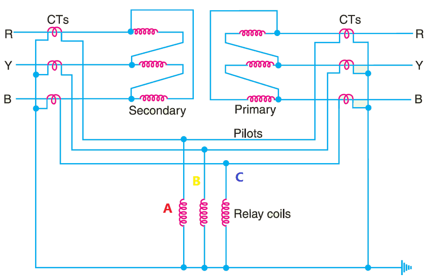
The two ends of the transformer both primary and secondary are connected with the current transformer. The output of the current transformer is given as shown in the figure.
In that, the relay operating coil A, B, and C are connected with respect to each phase and the CT neutral terminal. Here the vector sum of the current of each phase is equal to zero, hence the net current through the relay operating coils A, B and C is zero.
The relay becomes inoperative. During the abnormal condition, the current flow in both sides of CT becomes unequal.
Therefore, the unbalance current flows in the relay operating coil. if the current in the relay operating coil is higher than the pickup value of the relay, then the relay sends the trip command to the circuit breaker.
Conditions for Transformer differential protection:
While using these circulating current transformer protection, the following condition must be fulfilled.
CT ratio:
For percentage differential protection or normal differential protection, the Current transformer ratio in the primary and secondary winding should be the same.
But in the power transformer, we use it as either step-down or step up the voltage. So that always the current in the primary and secondary will be unequal. Hence the relay operates the circuit breaker even there is no fault.
This CT ratio will be eliminated by adding an interposing current transformer. The interposing current transformer matches the current between the primary and secondary CTs. It is connected to the star connection side of the current transformer.
Another method, that you can compensate for the difference in the magnitude of currents in the primary and secondary power transformer by matching their turns ratio of the low voltage winding.
Consider, K is the turn-ratio of the power transformer, then you can match the difference by the turn ratio of CTs on the l.v. the side is made K times that of the CTs on the h.v. side.
For example, Take a power transformer with a voltage of 110 kV/11kV. From that, you can calculate the turns ratio of 10. Now you are using CT of 200/1 on the high voltage side.
Hence the CT ratio becomes 200. For that, you have to use 2000/1 CT on the secondary side to match the magnitude of the current.
If you follow the above two, the secondary of the two CTs will carry equal currents under normal load conditions. Consequently, no differential current will flow through the relay and it remains inoperative.
Transformer Phase shift:
In a Power or distribution transformer, there is usually a phase difference between the primary and secondary currents of a 3-phase power transformer.
This exact angle of phase shift is mentioned in the transformer’s nameplate details. Even, if you use proper turn-ratio, a differential current may flow through the relay under normal conditions and cause relay operation.
This phase shift can be overcome by connecting the CTs in the opposite configurations. Typically, if the transformer winding is star connected then you should use CT as delta connection, like that for delta connected winding you should use star connection of CT secondary.
Please refer to the table that you can help you for various type of transformer connection and their respective CT connection.

Tappings of the transformer:
Mostly power transformers use an on-load tap changer for adjusting the voltage level to constant. Hence the change in the voltage level affects the secondary current in the transformer.
If you increase the voltage level, the current becomes reduced, and vice versa. This tapping creates an unequal current in the CT secondary. Therefore, the relay starts malfunctioning.
To overcome this, the current transformer contains tapping on its secondary side. The tappings are being adjusted according to the voltage changes in the transformer. But it is practically not possible.
Effect of Magnetizing inrush current:
Magnetizing inrush current is nothing but a current which flows when you energize the transformer. Since starting the transformer has zero induced emf in the windings.
This current only comes in primary of the current transformer. It is very short and but heavy (app. 4 times of the transformer full load current) Therefore, this inrush current leads to relay misoperation.
Magnetizing inrush current misoperation can be easily resolved. Magnetic inrush current has more second harmonic current of approximately 70%.
Therefore, we can design a relay with only operates in fundamental components. However, it reduces the sensitivity of the relay.
Length of the pilot wire:
The pilot wire is nothing but a looping wire which is used to connect the CT and relay panel. Generally, a power transformer will be placed in the switchyard.
Which would be far away from the control panel. To connect and bring the Current transformer’s output from the switchyard, the cables are used.
These cables are called pilot wires. Change in the length of the pilot wire, which affects the performance of the relay.
To overcome this issue, we have to calculate the total resistance of the pilot wire. After calculating the resistance value, we have to match them by connecting the adjustable resistor.
By adjusting the value of resistance, the restraining and operating become balanced or balance to be done.
Key Concept of Merz price protection:
While applying the circulating current principle for protecting the power transformer or distribution transformer we should fulfill the above 5 conditions avoid inadvertent relay operation.
Example:
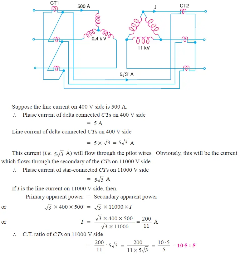
A 3-phase transformer having a line-voltage ratio of 0·4 kV/11kV is connected in
star-delta and protective transformers on the 400 V side have a current ratio of 500/5. What must be the ratio of the protective transformers on the 11 kV side ?
Solution:
For star/delta transformers, CTs will be connected in delta on 400 V side (i.e. star side of power transformer) and in star on 11,000 V side (i.e.delta side of power transformer).
Video Explanation In English of differential protection for transformer:
Video Has Taken under section 101 fair & education usage act.
Also see:
- Merz Price Differential Protection for Generators
- Neutral Voltage Protection -59GN- 95% stator Earth fault protection
- CVT in Electrical Capacitive Voltage Transformer CVT
- Difference Between Current Transformer & Voltage Transformer
- Droop CT – Droop Current Transformer
- How to Read CT Current Transformer Nameplate Details
- Potential Transformer Working Principle
- Relationship of Frequency Vs KVA Output or Rating of Transformer
- Three Phase Transformer Vector Grouping Significance of Vector Grouping
- Transformer Bushing Operating Principle
- Transformer Core Construction Details
- Trip Circuit Supervision TCS Relay Working Function and Operation

 and No Voltage Relay Working Principle")


 Chart – Transformer Wire Amperage Table")


Well written article with example and clear diagrams. It was useful to me. Thank you!
Thanks Dheerendra
helpful article!