Plug Setting Multiplier & Time setting Multiplier Calculation:
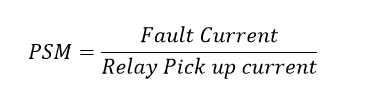
Plug setting multiplier is nothing but a ratio between the actual fault current in the relay operating coil to pick up current (the relay current setting).
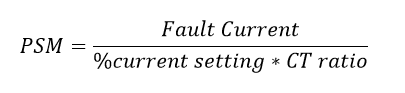
Relay pick up current= %current setting * CT ratio
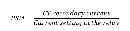
In other words, the ratio between the CT (current transformer) secondary current to relay operating current is called plug setting multiplier (PSM).
Significance of Plug setting Multiplier:
In the electromagnetic relay, the current setting can be done by adding resistance value. This action is performed by inserting plugs. The resistances are connected in series with the relay operating coil.
The plug is a small short link that connects the relay operating coils and resistance.
The high number of plug position increases the resistance value, therefore to operate the relay coils which need a high value of current to energize.
At the same time, the lower number of plug positions would be of less resistance, hence to operate relay coil, which needs low current value.
Therefore, The plug position ensures the current setting value of the relay. Plug setting multiplier (PSM) Indicates the severity of the fault.
The plus setting multiplier is used only in electromagnetic relays, not in numerical relays. Therefore, the numerical relay does not require plugs.
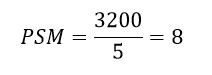
Example: If the plug position 5 means the relay operates when the fault current is 5 times of the CT ratio. i.e The supply CT is rated 400:5A and the fault current will be 3200A means, the plug position is 5 then the relay operates, because of the relay gets the current value of 25 Amps.
The operating Times is depending upon the PSM. The high value of PSM indicates low operating time.
Refer to the table below. The psm Value is normally available in the relay itself.
In our case PSM is 8, hence the relay trip the circuit in 2 seconds wheres the TMS is 100%. The Time setting multiplier is explained below.
| PSM | 1.5 | 2.5 | 3 | 5 | 8 | 10.5 |
| Time in sec | 10 | 8 | 5 | 3 | 2 | 1 |
Time Setting Multiplier (TSM):
What is TMS or Time setting multiplier:
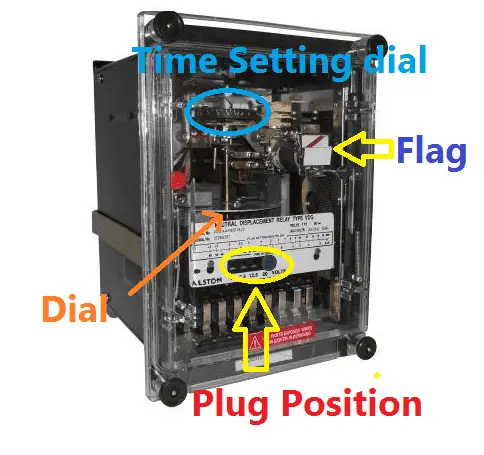
The time setting multiplier is nothing but an adjusting or speeds up the tripping mechanism of the relay (it is called as the dial).
The dial is nothing but a rotating disc, which rotates when the fault current in the relay coil reaches the pickup current.
It means, one end connects with the tripping mechanism and another end connect with the relay operation mechanism.
By changing the dial or disc position we can increase or decrease the tripping time of the relay. Refer the below TMS picture,
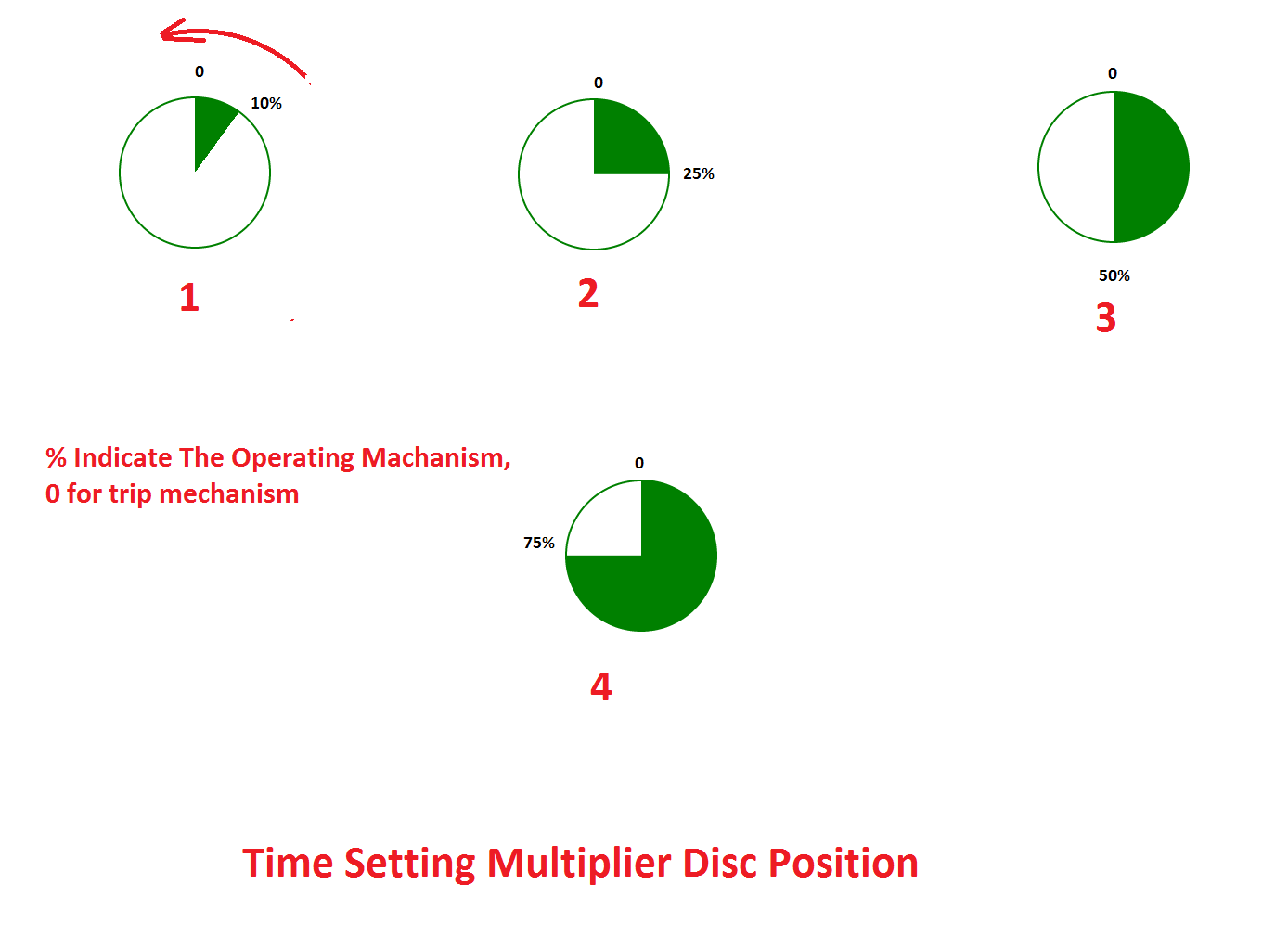
Here the position zero indicate the tripping position and green colour shade indicate the operating position. In the first disc, position indicates the TMS is 10%.
It means the relay operating time is 10% of the Plug setting multiplier time. Time setting value will be 10%, 25 %, 30 % …100% like that.
The total relay operating time= Plug setting Multiplier time (Which is available in the relay) * Time Multiplier Setting
Take an example of the above mentioned, in this, consider relay TMS is 10% and PSM=8.. Hence the timing for PSM 8, Time =2 sec…then the relay operating time is 2 * 10% = 0.02sec.

 and No Voltage Relay Working Principle")


Design a Simple dc supply circuit using a 220Vac to 110Vac transformer, 10A on the secondary to produce a fixed and clean 110Vdc