Directional Over Current & Non Directional Over Current Protection Working Principle:
Directional Earth Fault Relay is used to protect the transformer/generator/alternator from over current fault. The relay sense the fault current in only one direction, the relay does not operate when the current in opposite direction. Due to high cost, the Directional Earth fault Relays are used only of high sensitive electrical machine such as alternator & High voltage transmission lines.
Working Principle of Non Directional & Directional Over Current Protection:
First of all, what is over current relay? The relay operates when the fault current exceeds the pickup current. For Directional Over current relay, the fault current can flow in both the directions through the relay either forward or reverse, depending upon fault location. Therefore, it is necessary to make the relay respond for a particular defined direction, so that proper discrimination is possible. This can be achieved by introduction of directional control elements. During the opposite flow of current the CT polarity reverses, the power measuring device in which the system voltage is used as a reference for establishing the relative phase of the fault current.
Non Directional & Directional Over Current Relay Explanation:
Case: 1
[wp_ad_camp_1]
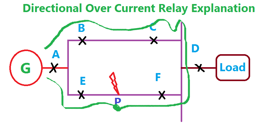
Consider a Power system consists of 6 circuit breaker A, B, C, D, E and F. In this, A, B, C, E are the Non directional over current relays and D, F is a directional over current relay. Consider a fault occurs at a point P. You should remember one thing first, the current always flow through the low impedance path. Hence the fault current flows from the generator G through the breaker A and E. Also the fault current comes from the breaker series A, B, C, and F. In this, the directional relay F operates the breaker of F, but the remaining all relay operates the respective circuit breaker in non-directional relay. Here the directional Relay D become in operative, because the load only observes the current.
Case 2:
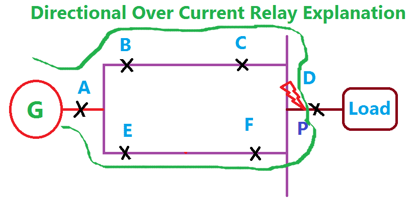
Now the fault occurs at a point P which is nearer to the load. In this case, the fault current flow from the generator through A, B, C, P, & A, E, F, P. In this condition, the relay A, B, C & E operates their respective breaker in Non-directional operation. D & F become in operative.
Case 3:

[wp_ad_camp_1]
Now we are using another generator G2, in place of load. Consider the fault occurs in P nearer to the generator G2. Now the current flow from G2 & A, B, C, D, P, & A, E, F, D, P. In this condition, the relay A, B, C & E operates their respective breaker in Non-directional operation. D operates the Circuit Breaker D on directional over current. F become in operative because the current direction remains unchanged.
Direction Over current relay ANSI code: 67
Non- Direction Over current relay ANSI code: 67 NC
Directional Over Current & Non Directional Over Current Protection Video Explanation:
More Subscribe: https://www.youtube.com/channel/UCXFxwj7DwumpUu5RNWlznTw

 and No Voltage Relay Working Principle")


