Transformer Core:
Generally, transformers are consisting of copper winding such as primary winding, a secondary winding, and auxiliary winding or tertiary winding, electrical insulation, core, bushings, insulation, terminal box, etc.
Transformers are working under the principle of mutual induction. Mutual inductance is nothing but a flux linkage between two winding. The magnetic flux is going through a structure which is called Transformer core.
Transformer cores are the main path of the magnetic circuit. Simply as compared to the electrical circuit, we can say it as the conductor.
How the conductor carries the current in the electrical circuit as well as in the magnetic circuit, transformer cores carry the magnetic flux.
The transformer core has less reluctance. Reluctance opposes the flow of magnetic flux. So That transformer core should have less reluctance.
The high value of reluctance increases the transformer core temperature.
Consider ration of Selection of transformer core:
- The transformer core should have less reluctance to the magnetic flux. The flux is indirectly proportional to the reluctance.
- The transformer’s core should be laminated in order to reduce the eddy current losses. The eddy current loss is proportional to the square of the thickness of laminations. The thickness of the lamination is made around 0.3mm to 0.5 mm reducing the thickness of the lamination below 0.3 mm leads to less mechanical strength.
- Higher content silicon steel is a soft iron material having less hysteresis loss. Also, the permeability of the silicon steel is high, therefore that material takes a small amount of magnetizing current. The steel used for transformer cores may be hot rolled or cold rolled. The hot rolled steel allows the maximum flux density of 1.45 Wb/m^2 and cold rolled steel permits the maximum flux density of 1.8 Wb/m^2 at 0.33 mm (or 0.35 mm) thickness. At that same time, the cost of cold-rolled steel is higher than the hot rolled steel. But cold rolled steel has many advantages that hot rolled steel iron..let see..
- Cold Rolled Grain Oriented (CRGO) steel sheet with an approximate silicon content of 3% is typically used for magnetic circuits of a transformer
- Magnetic induction is maximum and the loop of the BH curve is large.
- Core loss during no-load operation of the transformer is low.
- Reactive power input at no load operation of the transformer is low.
- Good mechanical strength
- Less magnetostriction
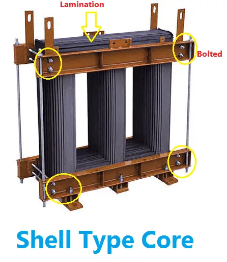
Transformer Core lamination:
Transformer stamping is connected and should be closed to flow magnetic flux. So that four types of construction is made.
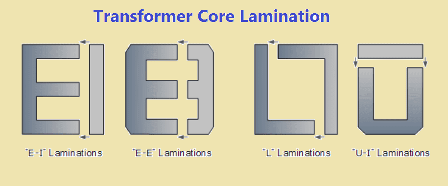
- E-I lamination
- E-E lamination
- U-I lamination
- L-L lamination
Here the English letter mentions the shape of the lamination. E-I and E-E construction is used in shell type transformer. U-I and L-L construction is used in the Core type of transformer.
E-I core laminated transformer construction is mostly used in isolation transformers, step-up and step-down transformers as well as autotransformers.
Note: Individual laminations should be tightly bolted during the transformer core construction. Allowing the air gap between the lamination leads to increases in the reluctance of the magnetic circuit.
Also For reducing the transformer noises, the lamination should be tightly clamped together and punch holes should be avoided as far as possible to minimize cross flux iron losses.
The air gap at the joint of limbs and yokes should be reduced as much as possible for allowing maximum smooth conducting paths for magnetizing current.
Transformer core Loss:
Transformer core losses are called constant losses which include both eddy current losses and hysteresis losses.
Both losses occur due to the reluctance of the core because we cannot construct a core with zero reluctance. (just like voltage drop in the electrical circuit. The voltage drop occurs in the cable due to the cable resistance)
Eddy current losses:
Eddy current losses are a constant loss due to the flow of circulating currents other than the core area. All the flux produced in the primary winding cannot reach the secondary winding, the flux is cut by the core neighboring parts.
Due to this action, there is a small amount of circulating current forms. Due to this current cause the loss. This loss is called eddy current losses.
Eddy current losses within a transformer core cannot be eliminated completely, but they can be greatly reduced and controlled by reducing the thickness of the steel core.
Hysteresis losses:
Each material has its own molecule structure. Transformer Hysteresis Losses occurs due to the friction of molecules against the flow of the magnetic lines of force required to magnetize the core, which is constantly changing in value and direction first in one direction and then the other due to the influence of the sinusoidal supply voltage (Alternating current).


 Conversion Calculator DC, 1 Phase, 3 Phase")