VFD Start Stop Wiring Diagram:
I am here with giving you a VFD start stop wiring diagram for running a VFD through panel board push button and keypad of the VFD (It is called HMI).
Vfd is a short form of variable frequency drive or variable voltage variable frequency drive. The VFDs are working based on changing the input frequency and input voltage of the motor, we can change the speed of the motor. Therefore by changing the voltage across the motor, we get save some input power of the motor.
P=1.732*V*I*Cos (power factor)
Three main use of this is Smooth starting, Variable speed and Power saving. It is better than starters. But we cannot start the vfd like normal starter. It requires some control logic circuit. Normally panel builders will take about these things the wiring + other accessories. Please read it fully do not miss out. With drawing you can do it by yourself. This is fully practical oriented drawing, while doing this make sure about your precaution measures (earthing and other protection).
Also see the details of the same vfd all way of starting local, Remote push button and DCS (Distributed Control System) /PLC (Programmable logic control) start-stop.
Why VFDs are required:
- Smooth starting
When we start the motor with DOL or Star/delta or Autotransformer starter the starting current goes 5 to 7 times of its full load current, which means it draws that much current from the feeder. So that voltage drop occurs throughout the PCC (power control center) or MCC (motor control center). In order to avoid this, we can use VFD instead of this conventional starter. It will start at 0 rpm (revolution per minute). This is very useful for higher HP motor.
- Variable Speed:
We Can operate the motor at any rpm. Motor speed N=120F/P here N=>rpm, F=>frequency, P=>number of poles
By changing frequency, we run the motor at any speed.
Required Materials to build vfd start stop wiring diagram:
Push button: 2 (Stop=1/start=1)
Indication lamb: 3 reds, 2 yellow, 2 green,
MCB 2 pole, 2 Amps: 1
Note: While selecting of MCCB Just short circuit and over current protection is enough to this application. Earth fault protection is not necessary.
Control contactor: 1
Note: While selecting contactor, make sure its coil voltage range (230V), Frequency (50) and which type of power supply required.
Cable 4 sqmm multi stand flexible copper cable: 5 meter each colour R, Y, B
Cable 1.5 Sqmm multi stand Flexible Copper cable: Required
Connector: Required
Connector mounting C channel: 1 full length
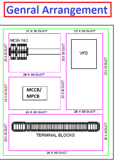
Starter control panel: 1 Size minimum LXDXH (400X450X400)
Note: All the above materials are example for the explanation purpose only, their range and quantity can be changed as per our load requirement.
How does vfd start stop wiring diagram Work:
Step: 1 Panel wiring
- Here MCB uses to control the input supply into the circuit.
- MPCB/MCCB uses to control input supply of your VFD,
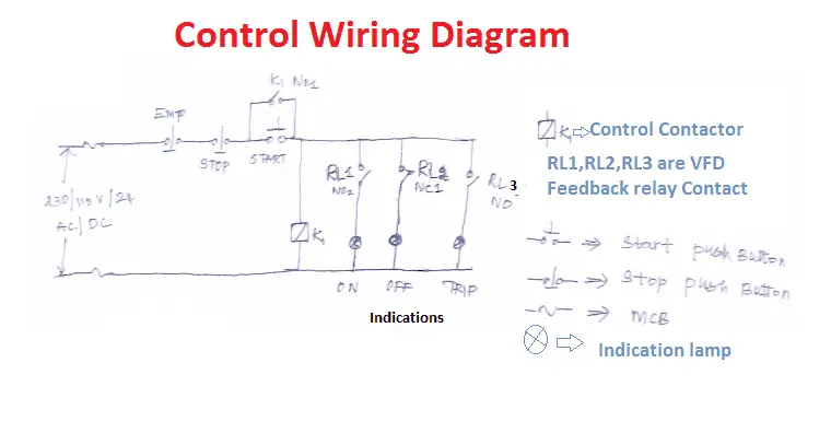
- Control the circuit by ON/OFF the push button
- RL1 and RL2 contacts should be taken from the vfd feedback relays.
Note: Some VFDs are having only one feedback relay, that time you just use the same for trip feedback.
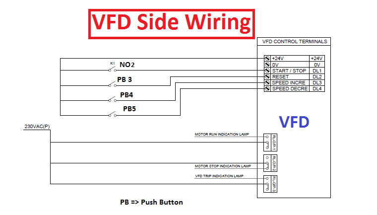
vfd start stop wiring diagram:
Connect or do wiring as per vfd side drawing, you take +24 V from the VFD PCB directly. K1 NO1, PB3, PB4, PB5 should be of potential free contact. When you press the on push K1 contactor will hold and K1 No1 become NC. Then as per vfd logic if DL 1(digital logic) goes high vfd start to feed the output voltage, motor start rotating. When You press stop Push button 2 then k1 contactor get release. then K1 NO1 become NO, Vfd stop output voltage. motor will be stopped.
When you press PB4 DL3 goes high and the output voltage and frequency will increase, it is not a inching operation. when you Keep hold the PB, output will increase, if you release the PB output remain same.
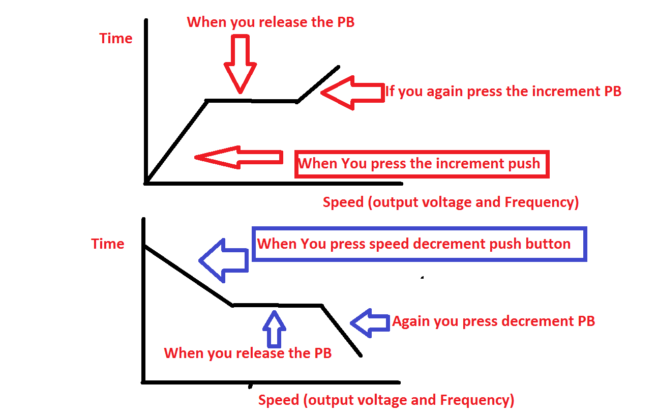
When you press PB5 DL4 goes high and the output voltage and frequency will decrease, it is not a inching operation. when you Keep hold the PB, output will decrease, if you release the PB output remain same.
PB3 work as fault reset. it uses to reset any type of faulty in the vfd.
Note: Before that you have to program your vfd to work as per the drawing. otherwise vfd start stop wiring diagram does not work.
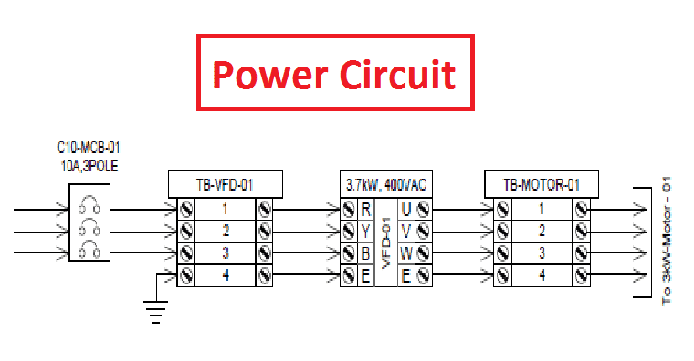
Power circuit:
Build Power circuit as shown the drawing. Do not forget to connect earthing of the VFD.
Step: 2
- Build or construct the vfd start stop wiring diagram as shown in the figure
- Mount Push button and Indications accessories on the panel door.
- Do commissioning on control circuit (first check control circuit)
- Switch on Power supply (Single Phase Supply vs Three Phase Supply) to the VFD and do programming with the relevant data.
- Take the trail without load.
- Once completed, Make Power connection.
- Take Load Trail
- Enjoy…
Further doubt please comment me….


Please send me one simple 3 wire start/stop control with one NO and one NC push button for ABB ACS355 4.1 amp drive.
Terminals are -24V, GND, DCOM,DI1, DI2,D13,DI4.
Sir,
I understood your explaination. But how to program in vfd as per drawing.plz let me reply.
Explanation is outstanding 👍👍
Thanks for the valuable work