What is Start delta starter:
Star delta starter is used to start the three-phase induction motor at star connection and after a few seconds, the motor connection will be changed to delta connection. The continuous operation will be held in delta mode. Generally, start delta start is preferred for the motor capacity is more than 10 HP. Start delta starter consists of three number of contactors, MCCB/SFU/MPCB/CB, relays and panel boards.
In this article, we are going to discuss Why star delta starter is preferred, circuit diagram, working principle, and application.
Why star delta starter is preferred for higher HP motor:
As we discussed earlier in the DOL starter, the three-phase induction motor draw’s high amount of current at the time of starting. The flow of higher current causes motor failure as well as a sudden voltage drop in the power system for a few milliseconds. The main purpose of the start-delta starter is to reduce the starting current of the motor.
Lets we see how star-delta starter reduces the starting current,
You know the 3 phase induction motor Torque equation such as
Consider,
I1= Starting Current of the Induction motor
V1 = Input phase Voltage
T => Starting torque
Here, full load torque can be achieved at the delta connection. In star delta starter, Delta connection indicates the motor terminals are directly connected to the three-phase power the same as DOL connection.
![]()
By referring the equation 1,
The torque is directly proportional to the square of the line voltage, by reducing the input voltage of the motor, we can reduce the starting torque of the motor,
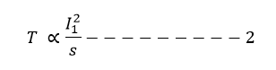
At the same time refer the equation number 2
The starting torque is directly proportional to the starting current of the motor, hence by reducing the voltage affects the starting torque and reduces the input current indirectly.
Note: At that time of motor staring, the slip s will be maximum, approximately s=1
This is the basic working principle of star delta starter.
Ok then, how much current can be reduced at starting in the starter? Let see..
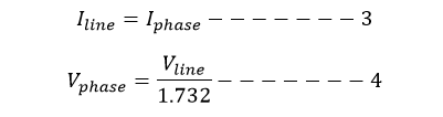
You know the current and voltage relation at star connection,
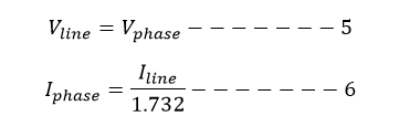
At delta connection,
At the time of starting the motor runs in star connection, therefore the phase current is equal to line current. But the phase voltage will be 1/1.732 times of line voltage due to star configuration.
Lets we compare,
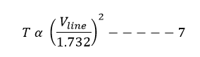
The starting torque at star connection
Apply equation 4 in 1,
Then Torque T is
The starting torque of the motor, if it is connected in delta connection,

Compare equation 7 and 8
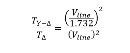
By solving the above equation,
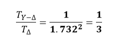
The starting torque at star delta connection will 1/3 times of the direct delta connection.
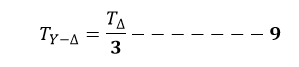
By applying equation number 2 in no 9,
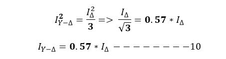
By referring to equation 10,
The staring current at star delta connection will be reduced by 57% of the direct delta connection.
Star delta Connection circuit diagram:
Star delta starters consist of a power circuit and control circuit. The power circuit uses to create contact between the motor and three-phase power supply. The control circuit uses to control the starter circuit such as ON, OFF and tripping operations. Refer to the below star delta circuit,
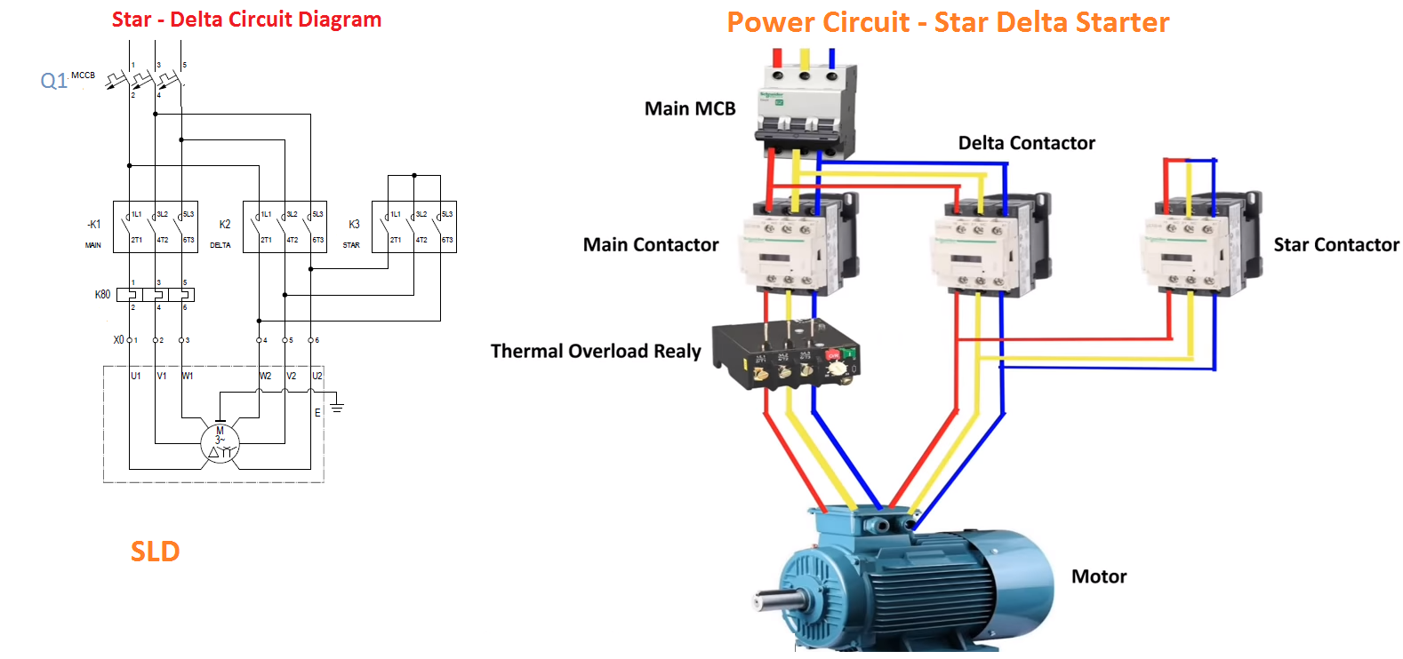
Power circuit
Power circuit consists of
- MCCB Q1 – One Number; while selecting the MCCB, it should able to withstand the motor high starting current and it should work as back protection for the motor. The rating should be 150% of the full load current.
- Contactor – 3 Numbers are used. Here 2 numbers of identical contactors such as one is for Delta connection (K2) and Main connection (K1). The third contactor uses for Star operation (K3) and the one end of K3 contactor will be short circuited for performing star operation. Mostly AC3 contactors are used for circuit breaking and the rating should be more than 100% of the Full Load current. In each switch operation, the contactor’s tip- contact gets damages, if we use under capacity. Note that, the contact tips are costlier and it is about 70% of the contactor.
- Relays (K80) – One number of thermal overload relay is required. By adopting magnetic tripping in the thermal overload relay, the motor can be protected from overcurrent and short circuit fault. If the motor capacity is more than 100 HP, we recommend using CT operated thermal overload relay. Since the life span of CT operated relays are high. Relay can be 58% of the full load current.
Control Circuits:
The control circuit is a logic circuit to help us to interchange the motor operation from star to delta.
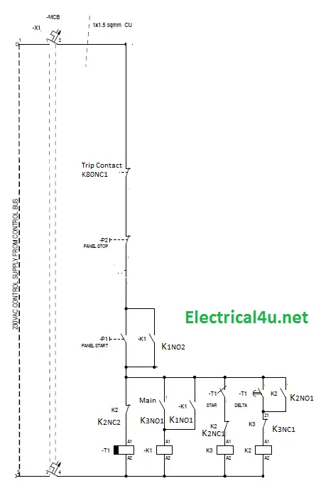
They are consisting of,
- Push buttons Two number – The green color is for Start – NO (P1) and red color for Stop – NC (P2), Here NO and NC terminology indicate Normally Open and Normally Closed
- Control MCB (X1) use to protect the control circuit.
- MCCB feedback contact Q1-1 No
- Timer T1 and Timer contact T2No. Here, timers are changing the motor connection from star to delta. A dial adjustment in the timer is used to adjust the delay time. In general, star-delta timer or off delay timer
- K80NC1 is a relay feedback contact. It is Normally NC => Normally closed and under fault condition, it will become NO.
- Other auxiliary contacts will be taken from the contactors K1, K2, and K3. These contacts are used to build the circuit diagram as shown in the figure.
- A1 and A2 terminal indicates the contactor’s coil connection.
Working Principle:
Power circuit working sequence: After pressing the green button, the motor star and main contactor will hold. Here the three-phase input directly going to MCCB => Contactor (K1 and K3) => Relay => motor terminal. At the same time, the Timer T1 starts, after reaching set value, The star contactor K3 will open and delta contactor K2 will hold immediately.
K1 and K2 contactor will be in hold position to run the motor continuously. In case, interruption in the power supply or fault in the motor means, the OLR K80 NC will open the control circuit. Then the motor stops.
Here one terminal of the star contactor will be short circuit as shown in the figure.
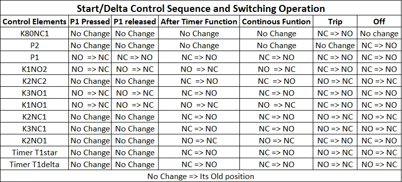
Control Circuit Working sequence:
Start Button (P) pressed:
Lets us assume, the start pushbutton (P) is pressed, Start Pushbutton (P) NO become NC, then the control current directly goes to Timer (T1) Coil, then T1NO2 goes to a Normally closed state. Immediately K2 – Star contactor will be closed. The control sequence is below table.
Video Explanation:
Advantage and Disadvantage:
Advantages:
- Cost is less as compared with other solid-state starters
- Life span is high
- Starting current has been reduced to 57%.
- No need to keep voltage reduction circuits
- Easy to Maintenance.
Disadvantages:
- Cannot be achieved higher starting Torque at starting
- Star- delta starters are having restriction to use medium /high Voltage motor.
- Power saving cannot be done.
Star Delta Starter – Practicality:
- While installing the thermal overload relay, the current setting should be calculated for phase current of the motor only.
- Putting the thermal overload relay in the output of the main contactor gives more effective and reduce in size and cost.
- The phase sequence must be properly checked. Negligence in this 100 % leads to motor winding failure.
- Putting Timer in the delta logic increases the timer life span.


, Types, Working")


