Difference Between Multi meter Megger and Series Test lamp:
Diagnosing electrical problem is very difficult task without these testing equipment. The three common and most used testing equipments are multi meter, Megger and test lamp. This three equipment are used to diagnose the electrical circuit problems, for different applications, i.e multi meters are used to check the circuit problem in electronics board; which means low voltage application; Megger is used to find the electrical circuit problem in high voltage equipment such as motors, transformers etc. and Test lamps are used to ensure the circuit problem which is checked by the Megger. In this tutorial, we are going to see the difference between multi meter, Megger and test lamp.
[wp_ad_camp_2]
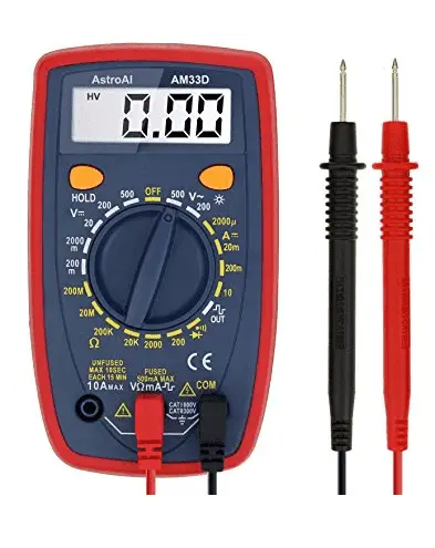
Multi Meter:
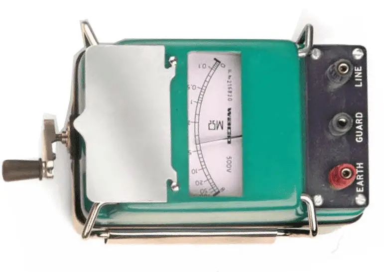
Megger:
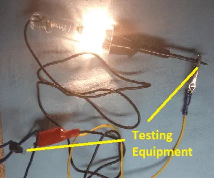
Test Lamp:
Difference Between Multi meter Megger and Test lamp:
Constructional Difference:
Multi meters are two terminal devices, which consists of positive and negative terminal, Megger is three terminal devices and which consist of Line, Guard and earth and series test lamps are two terminal devices.
Application:
Multi-meter is used to find out the fault is the electronics board, because of electronics boards are generally operated with the input voltage of 5 to 25 DC volts. Tracing faults on the electronics board by using high voltage does not give the accurate result. Since Multi-meters are generally preferable for fault tracing on PCB (Printed Circuit Boards), And low voltage applications equipment.
In case Megger, they are having ability to generate up to 7kV across the output terminal, since they are used to trace the faults on electrical circuits such as motors, transformers, cables etc.
Series test lamps ensure the problem on the electrical equipment, If an equipment fails on series test lamp method, the equipment never going to be charged. That will be considered as a faulty item.
[wp_ad_camp_2]
Working Principle:
All three equipments are working under the principle of short circuit and open circuit concept:
Short circuit: Current become high and voltage become low.
Open circuit: Current become Zero and Voltage become high.
Here, Multi meter just injects 5 volts DC to the output circuits, and receive some few micro ampere currents for the normal circuit under fault condition the Multimeters receives high amount of current typically few milli amps. Due to this variation in the current, the multi meter starts reading the resistance across the terminal.
Megger applies 700V to 5kV DC (Depending on the rating). Megger measure the Insulation resistance of the device.
Series test lamps are nothing but a 230 volts’ incandescent bulb (the bulb specification is depending on the application) is generally connected in series with the phase, load and neutral as shown in the figure. Under Normal condition, the test lamp does not get power from the source, but Whenever a fault in the load, the test lamp starts glowing. For better understanding please refer, the diagram.
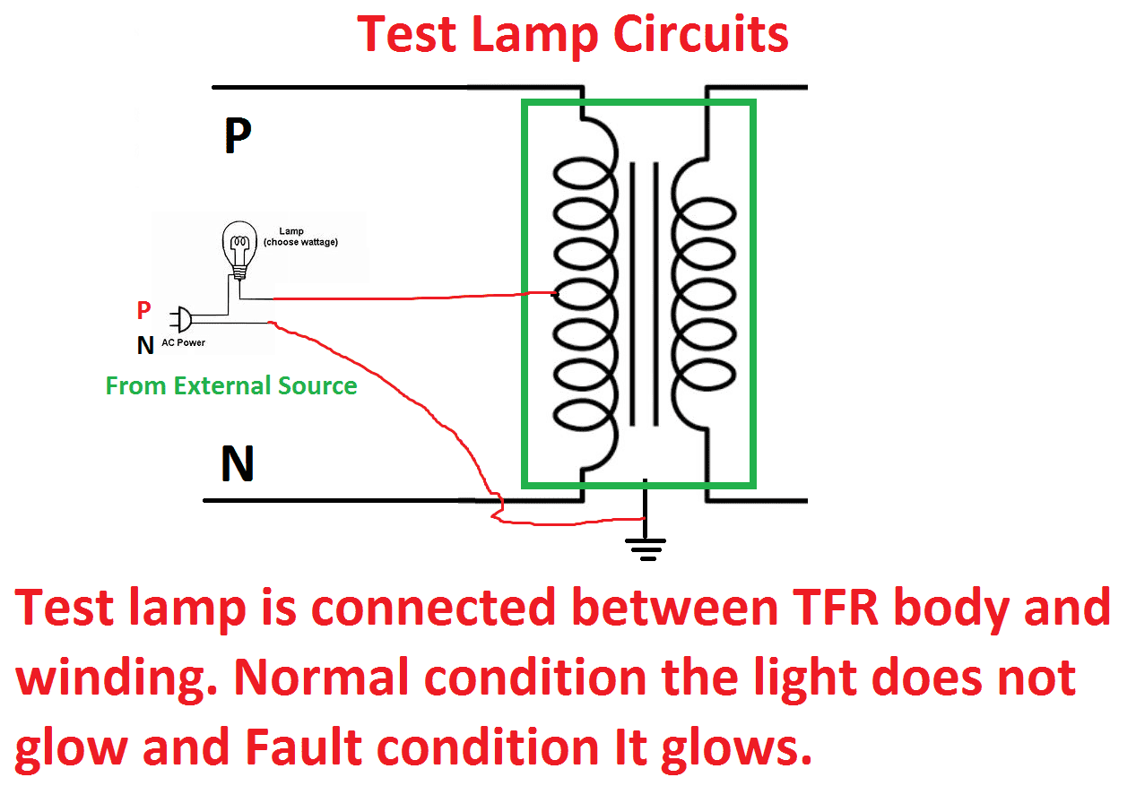
Observe the red color circuit, the terminals are having contact between phase and ground. During the normal condition the insulation resistance will be high, since the lamp does not glow, but during fault condition the lights starts glowing due to the current flows through the fault mouth.
Note: While using Those testing devices, the equipment (testing to be done) should be isolated from the input power supply.
Identifying Faulty Value:
The minimum value that will be obtain from the individual equipment to ensure the equipment faulty.
Multi meter: O.L
Megger: above 0.5 MΩ
Series Test Lamp: Bulb should not glow
Voltage rating:
Multimeters are not suitable for testing high voltage application, series test lamp and Megger are suitable for high voltage application.
[wp_ad_camp_2]
Source of the multimeter, Megger and series test lamp:
Mulitmere needs 5 Volts battery, Megger does not require any battery equipment (analog) but for digital Megger it needs 9V battery and series test lamp needs external source.
Accuracy:
Less in multi meter and Megger and series test lamp are having High Accuracy.
Safety measures:
Multimeter does not require but series test lamp and Megger produces high voltage, touching those terminal in with empty hand, cause electrical shock.
Output Measurement:
Multi meters and Megger shows the output values on digits but series test lamp shows the value in intensity of the light, The intensity of the test lamp is purely depending on the insulation resistance of the equipment.
Cost:
Series test lamp less cost as compared with Multi meter and megger cost. Hence
Megger > Multi Meter > Series test Lamp


 Conversion Calculator DC, 1 Phase, 3 Phase")
