DPDT (Double Pole Double Throw toggle):
A Double Pole Double Throw toggle switch is a combination of two individual SPDT (Single Pole Double Throw) switches connected in the single assembly. Look at the figure 1.2, the centre dotted line indicates that the DPDT switch is actually two SPDT switches in one package. They are mechanically coupled to control different circuits at the same time.
Here pole indicates individual input circuit and throw indicates the output circuit. Double Pole Double Throw toggle has 2 input terminals and 4 output terminals
DPDT circuit diagram:
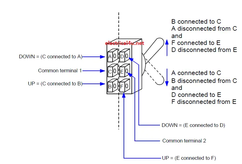
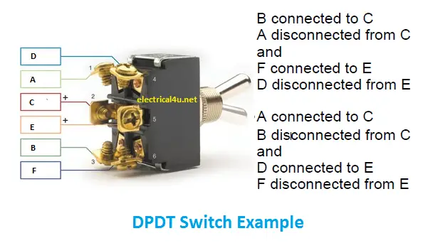
Look at picture 1.1 and 1.2, it consists of two common input terminals C, E and both mechanically tied together to operate in the same way. The input supply always is given to the common terminal C and E only.
Terminal A, B, D, and F are the output terminal and which will be connected to the outside circuit individually.
As default C will be connected with the terminal B and E will be connected with the terminal F. Both are considered as NC (Normally Closed), then the circuit associated with the terminal B & F will receive the input supply as default.
Terminal A and D will be in Normally Open (NO) as default; when you change the switch position the open becomes close.
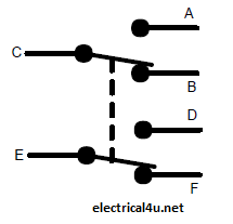
DPDT Schematic Symbol:
Operation of Double Pole Double Throw toggle:
Let’s take a simple circuit with two different inputs of lighting circuits and sound circuits. The input terminal B and E are connected to the lighting and sound circuit. The output terminal A, B, D and F are the output terminal and they are connected to Lamp, LED, Buzzer and Speaker.
Terminal C, A and B are the lighting circuit and Terminal E, D and F are the speaker circuit
There are two pictures, one is switch is in normal –UP ward position and another one is switched downward position with reference to fig 1.2,
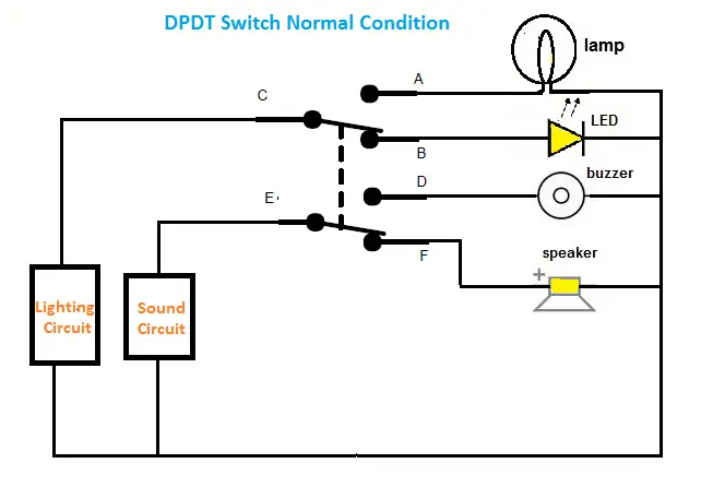
During Normal – Upward position, the lighting input terminal C is connected to the output terminal B, hence the current flows from lighting circuit to the LED lamp and it starts glowing. At the same time, another input E is connected to the sound circuit and whose output F is connected to the speaker and it starts working.
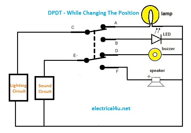
During the downward position, the lighting input terminal C will be connected to the output terminal A and the current flows from lighting circuit to lamps and it starts glowing. At the same time, the sound circuit input E will be connected to D, hence the buzzer starts working.
Meanwhile, the LED and speaker will be turned off, since the B and F terminal will go to Normally Open state.
Applications:
- Industrial selector switches.
- Breaker control logic circuits
- TG to Grid change over control circuits


 Conversion Calculator DC, 1 Phase, 3 Phase")

