CVT in Electrical Capacitive Voltage Transformer:
CVT Capacitive Voltage Transformer is a step down transformer just like potential transformer which converts high voltage in to low voltage. Capacitor Voltage Transformers convert transmission class voltages to standardized low and easily measurable values, which are used for metering, protection and control of the high voltage system. Normally in high voltage system, the line voltage or current cannot be measured. Therefore, instrument transformer such as Potential transformer and current transformers are generally used. At that same time in EHV lines (Extra high voltage lines) the cost of a potential transformer is high because of its insulation. In order to reduce the cost of the insulation the capacitive voltage transformers are used instead of standard voltage transformer.
The Capacitive voltage transformer (CVT) is also called capacitive potential transformer. Capacitive voltage transformers (CVTs) are used on higher voltage levels, starting from 72.5 kV and upwards.
Capacitive voltage transformer (CVT) Working Principle:
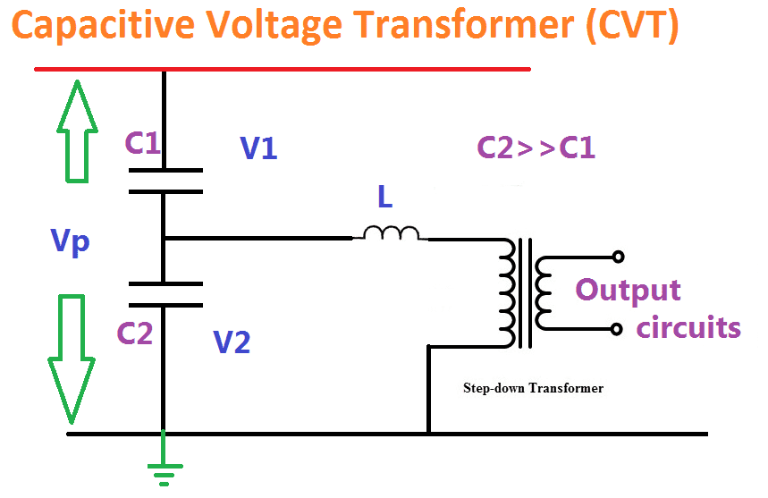
CVT is working under principle of potential divider. It consists of two capacitors to form a potential divider, line reactor and a step down transformer. Here line reactor is used to compensate the capacitor’s phase shift. The value of inductances is adjustable. The inductance compensates the voltage drops occurs in the transformer because of the reduction of the current from the potential divider. But, in actual practice, the compensation is not possible because of the inductance losses.
[wp_ad_camp_2]
The capacitor or potential divider is placed across the line whose voltage is be measured. Let the C1 and C2 be the capacitor placed across the transmission lines. C1 capacitor is nearer to the transmission line and C2 is nearer to the ground. The output of the potential divider acts as an input to the step down transformer. The capacitor places near to the ground C2 have high capacitances as compared to that placed near the transmission line. C2 > > C1. The high value of capacitances means the impedance of that part of the potential divider becomes low. Thus, low voltages pass to the Potential transformer.
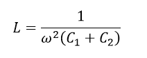
The Value of inductance can be calculated from..
[wp_ad_camp_2]
The voltage across the individual capacitor is V1 , V2 and the line voltage is Vline/1.732 =Vp as the potential transformer is connected across the line to ground.
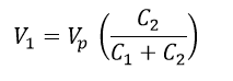
Hence the Voltage across the Capacitor C1 is, apply potential divider rule..
The voltage across the capacitor 2..V2..
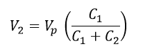
As the voltage across C1 is greater than the C2 exactly to say V2 < V1. Thus the value C1/(C1+C2) is small. The low value of voltage is obtained from the capacitor C2. The low voltage can be easily step down by the potential transformer.
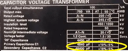
Name plate details of CVT: C2>>C1
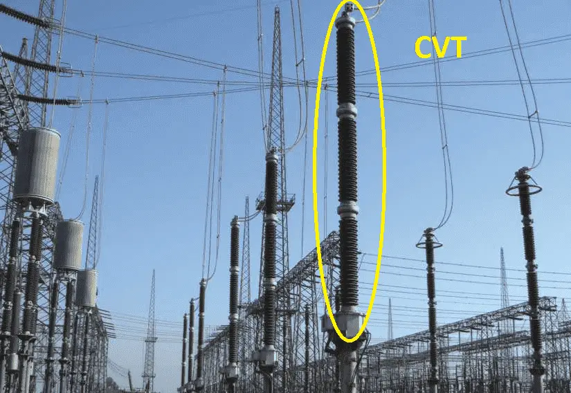
CVT Images in 720kV :

 and No Voltage Relay Working Principle")


 Chart – Transformer Wire Amperage Table")


Thanks a lot, this was so helpful.