What is Transformer Core Saturation?
Before to know about transformer core saturation you must know about reluctance, magnetic flux, flux density, and mmf (ampere turn). Simply we can compare with the analog electrical quantity. In electrical circuit, Resistance, current and voltage (EMF). The same quantity in magnetic circuits are in the same order reluctance, magnetic flux and ampere turn (mmf). Lets see
Resistance => oppose the flow of electrical current
Reluctance => oppose the flow of magnetic flux
Current => flow of electron
Magnetic flux => the electric energy expands in to magnetic field. The field force is called magnetic flux.
EMF => electro motive force typically voltage
MMF => Magneto motive force. Typically, ampere turns
Simple understanding about magnetic saturation:
i.e in analog circuit copper or aluminium conductor carries the current, it has own internal resistance… this resistance opposes the flow of current and results line losses and the cable gets warm. Further If you increase the flow of current in the same conductor, the conductor may get damaged. The same principle is used in magnetic circuits. In magnetic circuit, the conductor as core, resistance as reluctance, current as flux density. In normal condition, we apply the voltage, the flux produced, the flux pass through the core and reaches the secondary or primary winding and produce counter induced voltage in the secondary or primary. Here The reluctance of the core is normally less. If the applied voltage increases beyond the knee point voltage, the flux density increases, but the core does not allow the flux to reach the secondary or primary winding. This is because of the properties of ferromagnetic materials. Instead of producing the counter emf on the secondary or primary winding, the core gets warm up. This is called magnetic saturation.
[wp_ad_camp_1]
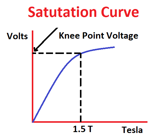
For iron core, if we increase the flux density more than 1.5 tesla, the iron core get saturate.
Formulated explanation of Core saturation:
Transformer’s core made up of soft iron material or powdered material etc. The core has own reluctance (in practically very low). In Normal transformer, When we apply a voltage across the secondary winding the flux is produced and the voltage is induced in the primary winding. Here the flux Φ is equal to
Here the applied voltage is directly proportional to the induced magnetic flux. Now you may get a doubt, if we increase the voltage in the secondary does it increase the flux? No because of Transformer gets saturate of increase primary voltage. Increase primary voltage has a consequence increase of intensity of magnetic field and magnetic induction until “knee point voltage” at the magnetizing curve. Beyond “knee point voltage”, if we increase the applied voltage, then the flux density also increases but magnetic induction stays almost equal like as before increasing of voltage (reaches steady state) or it increases a little (a lot less than in linear area). Please refer the saturation curve between the flux density vs Voltage.. This area of magnetizing curve is called area of saturation. Area of saturation is very dangerous area for work of transformer, because in this area ferromagnetic core temperature increases and it may damage the core.
Definition for Magnetic Saturation
The unit beyond which magnetic flux density in a magnetic area does not increase sharply further with increase of mmf.
From equ.1 the transformer core may get saturate with the high voltage with low frequency or high voltage or low frequency. In order to protect the transformer against core saturation the over fluxing or over excitation relay (ANSI 24) is being implemented. Normally the relay setting will be of V/f ratio. Normal value of v/f ratio of 110kV transformer is 2.2 (110/50) here 110 volts is potential transformer’s output and alarm value is 2.35 and the tripping value is 2.5. Generators or transformers are also specified to have the capability to withstand the over fluxing condition viz 110%- continuous; 125%- for 60 seconds; 140%-for 5 seconds.
[wp_ad_camp_1]
Another reason for core saturation is presenting DC component in the transformer excitation voltage. The dc components may come due to the natural point voltage is high. The natural voltage may increase due to interaction between the sun’s flares, earth magnets and poor quality of natural earthing. Railway transformers sometimes have problems with this since they are installed near railways -which if not properly grounded -may cause an elevated neutral voltage.
Key Point for Transformer core saturation:
- Core may get saturate when applied voltage increases or the input frequency decreases or both ratio changes
- DC component in the excitation voltage.
Also see:
- Percentage Differential Relay or Biased Differential Protection
- Power System
- Restricted Earth fault Protection 64R
- Standby Earth Fault Relay Operation 51N
- Transformer Core Saturation
- What is Neutral Why Neutral is required in Single Phase Power Distribution
- Why Capacitor and Inductor are used in Filtering Circuit
- Why Earth Pin is Plastic Thicker and Longer
- Why Earthing Transformer are used


