What is Partial Differential Protection:
Partial differential protection is used to protect the bus bar from over loading, provide the backup protection for main bus overcurrent protection and backup protection for all individual source circuits. Partial-differential Protection is a modified version of current differential protection. It is suitable for the only double ended substation which means two incoming circuit breakers with tie circuit breaker. It is not suitable for radial bus system.
Partial differential Protection Working Principle:
Partial differential protection works under the principle of differential protection and over current protection. In the concept of differential protection, the scheme compares two current input. The respective current transformers will be placed in two end of the device to be protected. In case partial differential protection, which sums the currents entering or leaving a switchgear bus through main and tie breakers. If a fault exists on the protected bus, the currents will add in the relays, but if fault current is flowing through the bus to a fault on another bus, the currents will subtract and the relays will not respond. If the fault is on a feeder, the partial differential relays will act as backup to the feeder overcurrent relays.
Also see:
- Bus Bar Differential Protection or Circulating Current Protection
- Busbar Protection & Frame Leakage Protection Working Principle
- One and Half Bus System & One And Half Circuit Breaker Scheme
- Generator and Transformer Unit Biased Differential Protection
- High Impedance Differential Protection Low Impedance Differential Protection
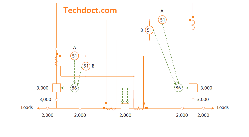
Partial differential Protection scheme:
[wp_ad_camp_2]
Example:
Consider a two main bus with single tie breaker. i.e main breaker consists of 3000Amps and tie breaker consists of 2000 Amps. The scheme consists of two over current relays A and B. The CTs on the main circuit breakers are connected to overcurrent relays 51A and 51B. Also the tie breaker current transformer is connected in parallel with the overcurrent relays 51B. Now 51A relays set for 3000A and 51 B relays are set to operate 2000A. The scheme works because the current which flows to the other end of the substation (through the tie circuit breaker) is subtracted from the current flowing through the main circuit breaker, and therefore the “B” relays see only the difference in current. When the tie circuit breaker is open, the “B” relays will provide protection for their section of main bus at the 2,000 A rating. The “A” relays only become a factor when the tie circuit breaker is closed and the current through the main circuit breaker is above 2,000 A. The scheme shown in Figure and the scheme works under three operating conditions.
- Two mains closed and tie open
- One main closed, other main open and tie closed
- Two mains and tie closed.
Now consider a short circuit fault on the load side, then the fault will be detected by the current transformer on main 3000A breaker side. Then the fault current will be added with the relay 51 A and 51B relays. Let we take the fault current as 5000A, load current through main source is 1500 Amps and load current through the tie breaker is 500Amps. During the fault condition, the main CT reads the current of 6500 Amps here the relay A gets the current value of 6500 (1500 + 5000) Amps and the B relay gets the current value of 6000Amps (1500-500+5000). Now we will calculate the effect of fault current (PSM) on both relays are A = 2.16 (6500/3000) and for B relays gets B = 3 (6000/2000). From this calculation you can come to which relays become faster. The B relays gets more effect than A relays. Here, B relays get operated because of the plug setting multiplier is indirectly proportional to operating time, then the increasing in the PSM, decreases the time delay. Hence the B relay much faster than A relay. This kind of scheme is called partial differential protection.
Only the purpose of this protection is that, to avoid additional time delay for the main circuit breaker to obtain selectivity. In a conventional scheme, feeder circuit breakers have one-time delay, the tie circuit breaker has additional time delay, and the main circuit breaker has even longer time delay for tripping. In this scheme, the extra time delay for the tie circuit breaker is avoided.
[wp_ad_camp_2]
Note: While using of Partial differential protection, the relay co-ordination with tie feeder and load circuits protection to be properly coordinated.
Also see:
- Merz Price Differential Protection for Generators
- Merz Price Differential Protection for Transformer
- Motor Protection Relay MPR Relay Working Principle Higher HP & High Voltage Motor
- Restricted Earth Fault Protection 64R Working Transformer
- Reverse Power Protection Working Principle -32R
- SOTF Relay Working Principle – Switch On To Fault protection
- Unit Auxiliary Transformer (UAT) Differential Protection 87UAT
- Percentage Differential Relay or Biased Differential Protection
- Mater Trip Relay 86 Working Function and Significance of Master Trip Relay
- Relay Codes for all Relay From 1 to 150 Numbers

 and No Voltage Relay Working Principle")


