Transformer Leakage Reactance:
In an electrical machine such as alternator, transformer, motor etc, the inductance is a responsible for creating flux in the machine. In the transformer, primary and secondary is mounted in the core structure and primary winding produces the magnetic flux and the same flux link to the secondary winding. In ideal transformer all primary flux is linking with secondary. However, all the flux in a transformer will not be able to link with both the primary and secondary windings (reverse and forward process). A small portion of flux will not link with the secondary winding, a small portion of the flux completes its path through, self-coil, air, winding insulation, insulation oil rather than through the core, and the flux which is not link with the secondary winding is called as leakage flux or magnetic leakage in transformers.
The leakage flux does not contribute to transfer of energy from primary winding to secondary winding. Instead of that the leakage flux produces counter emf in the respective coil due to self-reactance in the primary and secondary winding. The leakage flux affects the main working flux. This self-reactance of transformer is called as leakage reactance of transformer. The resistance and leakage reactance in the winding is impedance (reverse and forward process). Due to that impedance, there is a voltage drops in both primary and secondary winding. This voltage drop reflects in the output of the transformer. Hence reduction in the output voltage of the transformer both step up and step up process.
What is Percentage of leakage reactance or Impedance voltage?
Normally, the percentage of leakage reactance or Impedance voltage, mentions in transformer’s name plate details. Here the number, for example 2 % means whenever you load the transformer at 100 %. You will get the output voltage of 2% lesser. i.e if you have a transformer 31.5MVA, 110kV/11kV, 136 Amps, 2% leakage reactance means whenever you load the transformer at 100 % (136 Amps) then you will get the output voltage of 10780 Volts.
[wp_ad_camp_1]
Leakage reactance significantly says about the voltage regulation of the transformer.
Hence, the Leakage reactance in power transformer/distribution transformer is one of the important parameter for designing and choosing a transformer etc. Always you should choose low leakage reactance of the transformer to get maximum efficiency.
How to Measure leakage reactance?
Leakage reactance can be measured by short-circuiting any one of the winding of the transformer either primary or secondary but always low voltage winding is preferred to perform this test and increasing the voltage on the other winding until rated current flows in the windings. The voltage variations are done by modern power electronics equipment or Using a single phase high current low voltage source. Measure voltage across and current through an individual winding. This voltage divided by the rated winding voltage, then multiplying by 100 results to percent reactance or %X.
So leakage reactance is termed as, %reactance= (reactance voltage drop/winding voltage)/100.
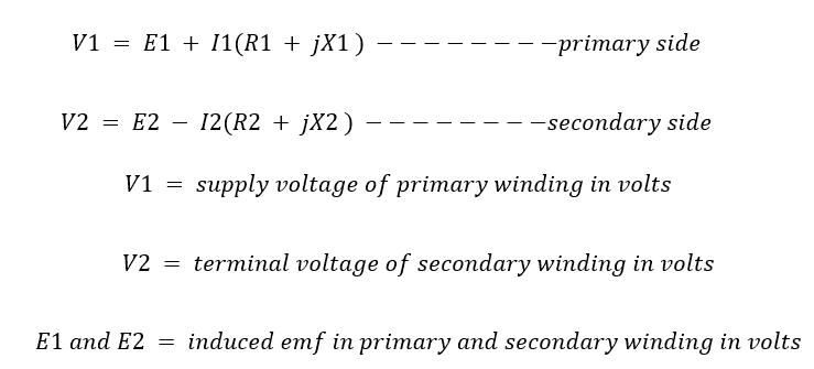
Here, R1 Primary Winding Resistance and R2 secondary winding Resistance in Ohms
X1 Primary leakage reactance and X2 secondary winding leakage reactance in ohms
Z1 and Z2 = Primary impedance and secondary impedance in ohms
![]()
[wp_ad_camp_1]
The impedance in each winding lead to some voltage drop in each winding.
Considering this voltage drop the voltage equation of transformer can be given as –


