Vector Surge Relay Working Principle:
Vector surge relay is used to protect the transformer/generator/alternator from grid disturbance such as grid failure, grid interruption, vector surge etc. Vector surge relay also called as main decoupling relay or simply MRN relays. It has many features such as under voltage protection, over voltage protection, under frequency and over frequency protection, and Vector shift protection. It is very Important protection in electrical power system.
[wp_ad_camp_2]
Working Principle of vector surge protection:
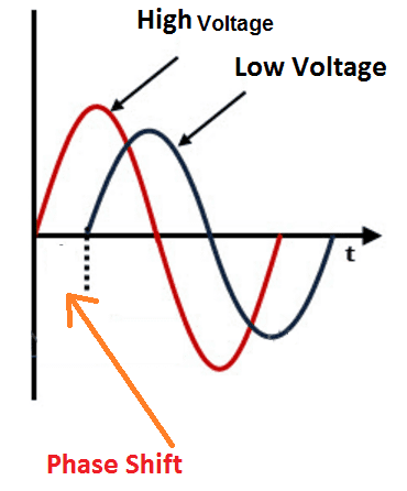
It senses the voltage across the two side of the power transformer. Normally power transformers or any other transformers are manufactured with vector group of Dyn11 or any other vector group. This is the core principle of vector surge protection during synchronization. Here vector group indicates that LV winding, which is star connected (written in small letters. means LV side and vice versa) is 30 degrees lagging by HV winding which is delta connected. See the picture of Practical implementation of Vector grouping. The low voltage winding has 30 deg. lagging with the high voltage winding.
Here the relay uses the same principle. The input voltage of high voltage winding and output voltage low voltage winding of the transformer is taken from the respective instrument transformer (potential transformers). Both are will be connected to the relay terminal.
Vector surge protection Operation:
During synchronized condition, the relay monitors the phase shift between the high voltage winding and low voltage winding & between phases. During fault condition, the fault associated with the phase shift some angle. The angle difference is higher than the present value the relay operates the circuit breaker.
[wp_ad_camp_2]
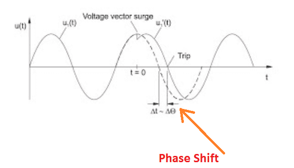
Here the phase shift of ΔΘ is the shifted angle during the fault.
Example take a three phase system each has 120 deg phase difference typically R= V∠0 deg, Y = V∠ 120 deg and B = V∠240 deg . let’s consider a fault (single phase to ground fault) on the R phase then the phase shift occurs some angle R = ∠10 deg. If you set the relay to operate on 8 deg on single phase, then the relay trips the circuit breaker.
Also see:
- Difference Between RYB and UVW
- ELCB Earth Leakage Circuit Breaker | Ground Fault Protection
- Electrical Panel & Types of Electrical Panels used In Industry
- High Impedance Differential Protection Low Impedance Differential Protection
- Generator and Transformer Unit Biased Differential Protection
- Merz Price Differential Protection for Generators
- Merz Price Differential Protection for Transformer
- Distance Protection Working Principle & Fault Location Detection
- Directional Over Current & Non Directional Over Current Protection Working Principle
- Restricted Earth Fault Protection 64R Working Transformer
- Standby Earth Fault Relay Operation 51N
- Corona Definition | Avoid Corona | Purpose of Corona Ring | Advantage
- CT Supervision Relay Working Principle
- Current Based Relay | Voltage Based Relay

 and No Voltage Relay Working Principle")


Dear Sir,
Please see the send your Quotation Immediate as Follow:
1) RELAY: MRG2, VECTOR SURGE VECTOR SURGE RELAY: MRG2
RANGE: NOMINAL VOLTAGE: UN 100V,230V,400V
FREQUENCY: fN40-70Hz
POWER CONSUMPTION IN VOLTAGE CIRCUIT:
THERMAL RATING: CONTINUOUSLY 2 X UN
UNDER VOLTAGE LOCKOUT FOR VECTOR SURGE MEASUREMENT: U < ADJUSTABLE(5%…10% UN)
DROPOUT TIME:60ms
TIME LAG ERROR CLASS INDEX E: +/-10ms
MINIMUM OPERATING TIME: 50ms
Max. ALLOWED INTERRUPTION OF THE AUXILIARY SUPPLY WITHOUT A FACTING THE FUNCTION OF THE DEVICE