WORKING OF 3 WAY SWITCHES
How do they work?
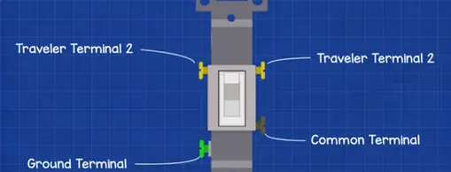
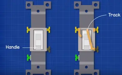
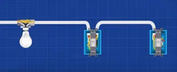
The 3 way switches has four screw terminals one is for ground, one is for common terminal, and other two terminals are traveler terminals. Inside the switches there track for electricity flows. This is connected to switch to handle. When we flip the switch handle track will flip between two traveler terminals. This will change the flow of electricity and we can control the light.
Circuit 1: light after the switches
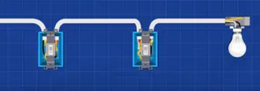
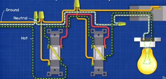
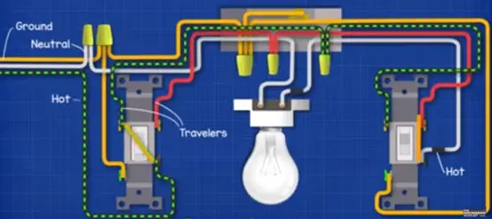
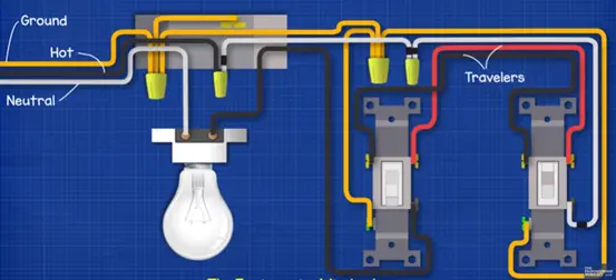
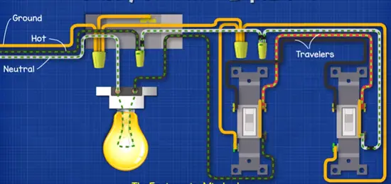
In this circuit we are going to look light after switches. The light is fitted at last in the circuit. For this circuit the following parts are required, they are 4* wire connectors, 2*3 way switches, 1 lamp fitting, 1 lamp, 2 switch boxes, 1 ceiling box, 3 wire cable, 2 wire cable, 2 switch box.
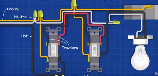
The hot black wire is connected from the incoming power source is connected to common terminal in switch1. Then from the traveler the black cable is connected to the left traveler2 in switch2. From the common terminal of switch2 over to ceiling box to light fitting.
Take the red wire run from right traveler terminal from switch1 and take this over to right traveler terminal to switch2.
The incoming neutral wire run into connector which is connected in the switch box of switch1 form this wire connector run the white wire and connects in switch box 2. Then connect the final white wire from wired terminal from switch2 and take this over ceiling box on to the light fitting to complete circuit.
For safety we connect the ground wire from the incoming supply connects this to wired connector to switch box 1. Then we run the ground wire from ground terminal of switch1 and connect this ground connector. We connect ground wire connector from switch box 1 in wire connector to switch box 2. Then run the ground wire from switch box 2 to ground wire connector swicth2. Finally ceiling box metal we will run a ground wire from the ground screw box and connect the ground wire in switch box 2.
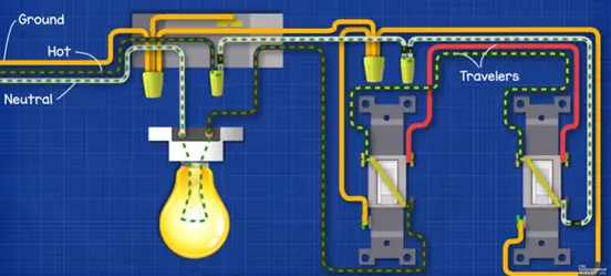
When we power the circuit the electricity comes from the hot wire and passes a switch1 along the black traveler wire to switch2. The switch2 is the opposition circuit is broken and light is OFF.
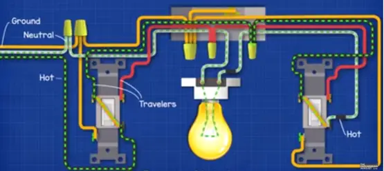
When we flip switch2 the track change direction and electricity flows across swicth2 through the light and back along the neutral wire.
We flip switch1 electricity flow across switch1 and to red traveler wire but it stop the switch2 as the tracks disconnected by flipping switch2 we again complete the circuit.
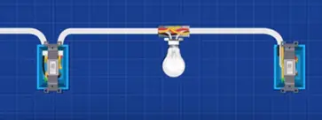
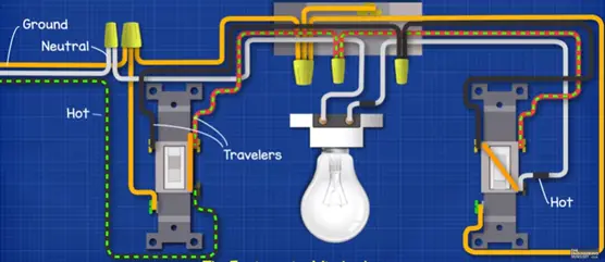
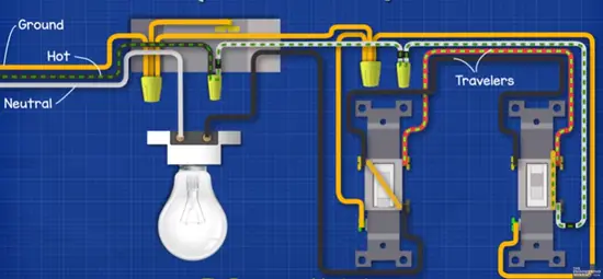
Circuit 2: light is fitted between switches
For this circuit the following parts are required, they are
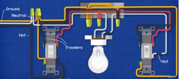
2*3 way switches, 3 wire cable, 2 wire cable, 1 ceiling box,1 light fitting,1 lamp, 2 switch box, 5 wire connectors, electrical tape.
From the incoming power supply connect the black hot wire common terminal switch1 then run the black traveler wire from left traveler switch1 take over to wired connector to ceiling box. Then we run another black wire from the wired connector connect to left traveler terminal of swicth2.
Then we run red traveler wire right traveler of switch1 connect this to wired connector of ceiling box. Run another red wire from wired connector to right traveler terminal of switch2.
Now bring the neutral wire from incoming supply to wire connector between switch box 1. Run another wire neutral wire from wired connector through ceiling box and connect to light fitting. Run the third white wire from the light fitting terminal and run this to the common terminal of switch2. The both ends of this wire insulate with black insulation tape to worn sleeves which indicates cable is live.
To make circuit safe we bring the ground wire to wired connector. Connect ground terminal switch1 into the wired connector and run another ground wire from wired connector and bring this to wired connector in the ceiling box as the ceiling box is made of metal connect to ground. Finally from ground switch2 run a ground wire from ground terminal to bring over ground wired connector in the ceiling box.
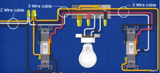
In a complete circuit we have a two wire cable in incoming supply in switch box 1 in between switch1 and switch2 the light fitting has three wire cables.
If we power the circuit the electricity flow through the hot wire across switch1 through ceiling box to terminal switch2 but circuit is broken in switch2 the light is OFF.
When we flip switch2 electricity flow across switch2 through the light and back through neutral wire. Flip switch1 electricity again will again make switch2 through red traveler and can get across switch2 but we flip switch2 it will complete circuit again and light will ON.
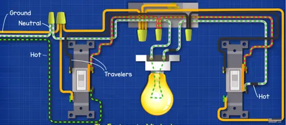
Circuit 3: light before switches
The following parts are required for this circuit; they are 2-3 way switches, 4-wire connectors, 1-light fitting, 1- lamp, 1-ceiling box, 2- switch boxes, 3wirecabel, 2 wire cables, and electrical tape.
Bring hot wire supply to ceiling box and connect to wired connector. Run a white wire from the wired connector to this wired connector in switch box 1. The both ends of this wire insulate with black tape in worn hot to indicate wire is live. Run another white from the wired connector connect common terminal of switch2 again mark with black tape. Run red traveler wire from the right terminal of the switch2 and connect to right traveler terminal in switch1. Run the black traveler wire between the left traveler terminals of the two switches from switch1. Run the black wire from common terminal to connect light fitting terminal.
To complete the circuit bring the neutral wire and connect light fitting terminals. To make circuit safe bring ground wire and connect to wire connector to ceiling box. The ceiling box is metal connect in the ground screw. Run another ground wire between the wired connector in switch box 1 from there connect switch ground terminal to wired connector. Finally run a ground wire from ground terminal of swicth2 over the ground wire connector.
In a complete circuit two wire cable in incoming supply before ceiling box and two wire cables before first switch and three wire cables before second switch.
When we power the circuit electricity can flow through the hot wire into the white wire over to switch2 it travels a longer way traveler to stops switch1. Flip switch2 electricity now flow across switch2 through the light fitting and return back through neutral.
Flip switch1 electricity can’t pass the switch so light off. Flip swicth2 again circuit complete and light will ON.

Content/Image Credit: https://www.youtube.com/watch?v=_u5ORnhqn8g


 Conversion Calculator DC, 1 Phase, 3 Phase")
 Calculator DC, Single Phase & Three phase")
 Electrical Unit?")
