Faraday’s law Electromagnetic induction:
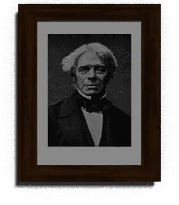
Electromagnetic induction was discovered independently by Michael Faraday in 1831 and Joseph Henry in 1832. Faraday was the first to publish the results of his experiments in 1831 August 29. Michael Faraday, was an English physicist who gave, one of the most basic laws of electromagnetism called Faraday’s law of electromagnetic induction. At first, the law was rejected due to lack of mathematical and theoretical calculations. This law says about the electric circuit and magnetic field. This principle is used in most of the electrical utility. As we know some of the applications names are electrical motors, generators, electrical transformers and magnetic control circuits such as contactor, relays etc.
[wp_ad_camp_1]
Faraday’s Law of Electromagnetic induction:
Faraday’s law of electromagnetic induction law stats that the emf induced in a closed electric circuit is equal to the rate of change of flux linkages.
Here N is the Number of turns in a coil and Φ is the flux linking with all of them.

In most of the cases, the flux Φ does not link with all the turns, under these cases, the summation of all products of magnetic flux with the complete turns of the magnetic circuit gives the total value of flux linkages…
Hence the total value of flux linkages is ..
Here Nk is the number of turns which link with flux Φk.
In case there is a change in the value of the flux linkages of the coil, an induced emf is produced in it whose value is given by…
Here the negative sign indicates that the direction of induced emf is such that the current produced by it opposes the change in flux linkages.
The change in the flux linkages can be caused by three ways.
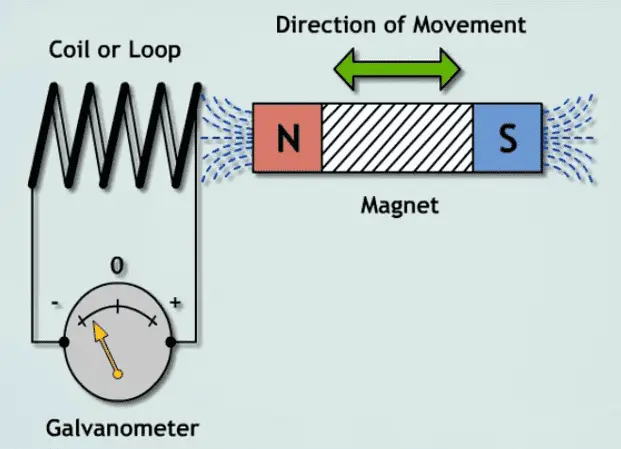
- The Coil is stationary with respect to flux and the flux varies in magnitude with respect to time.
In this method, where the coil or turns is a stationary (the coil do not attain any movement action) and the flux is time-varying, here an emf called transformer or (pulsation) emf. Since no motion is involved, there is no energy conversion and the process that really takes place is energy transference. This principle is used in transformers which employ stationary coils and time-varying fluxes for transfer of energy at one level to another level.
Example: Transformer.
- The flux is constant with respect to time and is stationary and the coil moves through it
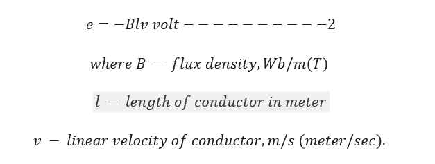
In this, the flux cutting rule can be employed to illustrate the emf generated in a conductor moving in a constant stationary field. The emf generated in a conductor of length moving at right angles to a uniform, stationery, time invarying magnetic field is given by
[wp_ad_camp_1]
The generated emf , in this case,is called a “motional emf because it is caused due to motion of a conductor. Since motion is involved in the production of this emf, the process involves electromechanical energy conversion. This principle is utilized in rotating machines such as DC machines, AC machines such as induction and synchronous machines.
Example: AC motors, Generator, etc
- Both the changes mentioned above occur together i.e., the coil moves through a time varying field.
In this the conductor or coil is moving across a stationary time varying magnetic field (flux) and therefore both transformer as well as motional emf are produced in the conductor or the coil. This process thus involves both transfer and conversion of energy.
Example: Commutator machine.
Key Points:
- To induce emf in a coil or conductor, the conductor should be in the momentary position or the flux should change with respect to time.
Example for conductor movement machine: generator and alternator
Example for time varying flux machine: Transformer
- The rate of change of flux is directly proportional to induced emf.
How to increase induced emf in the coil
You can increase induced the emf in a coil by four ways
- Increasing the number of Turns increase the flux linkages in the circuit, when the flux linkages increases automatically increase the induced emf.
- Increase the speed of the conductor. The frequency f says about the speed of the conductor. Typically, in the synchronous machine, it is called as synchronous speed.
- Increase the flux density of the circuit increases the induced emf in the conductor. Refer formula 2
- Increasing the length of the conductor increases the induced emf in the coil. Refer formula 2.
Video Explanation of Faraday’s Law Electromagnetic Induction:


![What is Arc Chute? Types, Working Principle [Video Included] arc chute working priciple](https://www.electrical4u.net/wp-content/uploads/2020/06/arc-chute-218x150.png)