What is high impedance differential protection and Low Impedance differential protection:
Generally, you can configure your differential protection in two ways, according to the connection, the CT ratio, CT burden and Contributing current to the other circuit devices such as meters, another control panel etc. Let see the configuration
- High impedance differential protection
- Low impedance differential protection
In this tutorial we are going to see what is high impedance differential protection, low impedance differential protection, how to configure the CT connection and significance of stabilizing resistor calculation etc.
First of all what is impedance, what is high impedance and low impedance?
Impedance (Z):
Impedance (Z) is nothing but a ratio between the voltage and current in AC circuits. Consider Voltage V and Current I then impedance Z is
What is high Impedance:
High impedance is nothing but a where the impedance value of the circuit is high which means when the circuit operates in high voltage with low current is called high impedance circuit.
[wp_ad_camp_1]
![]()
Low Impedance:
Low impedance circuits are exactly opposite to the high impedance circuits, which means the circuit operates low voltage with high current such a circuit is called Low impedance circuit.
![]()
Let come to our case.
What is high impedance differential protection?
Where the differential protection relay coil operates in high voltage with low current such relay is called high impedance differential protection relay.
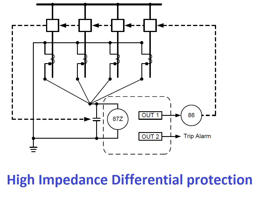
High-impedance bus differential relays are applied to the paralleled output of all CTs from each phase connected to a common bus. As the name implies, the high-impedance bus differential relay presents a very high impedance to the flow of current. To establish high impedance differential protection, we should satisfy some important conditions. Let see..
- The parallel CT must have same CT ratio
- The CTs must be connected in same polarity
- Burden of the all parallel CTs should be same. In order to avoid the voltage, drop across the CT
- CT accuracy should be same
- CT should not be shared with other circuit’s equipments
- The connection configuration should be as follow.
From the circuit Any current difference is forced through the high impedance of the bus differential relay causing a voltage drop across the relay. The high-impedance relay, which is calibrated and set to trip based on the voltage across the relay, is extremely sensitive to CT difference current. For this reason, not only must the CT ratios match, but the CT accuracy ratings must also match to minimize the CT performance differences that could create CT difference current.
[wp_ad_camp_1]
What is Low impedance differential protection?
Where the differential protection relay coil operates in low voltage with high input current such differential protection is Called low impedance differential relay.
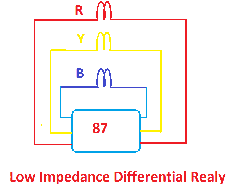
Low-impedance bus differential relays are so named because the differential relay current inputs have a low impedance to the flow of CT secondary current. This means that the low-impedance bus differential relays can share the CTs with other relays, meters, transducers, etc. The low impedance bus differential scheme typically has one set of current inputs for each phase from every set of CTs. Please refer the drawing.
Refer the circuit diagram, all the CTs R, Y and B is configured like this. Each CT is having their own tripping coil.
Having individual current inputs also allows the circuits comprising the differential zone to have different CT ratios, an important attribute where the CTs are shared with other protection and monitoring functions.
Low impedance differential Protection conditions:
- Paralleled CTs must have the same ratio.
- Only CTs on load circuits can be paralleled without risk. Paralleling CTs on circuits with external sources of fault current increases the risk of unwanted relay operation for through-fault conditions.
- The combined maximum load current from the paralleled CTs must not exceed the continuous rating of the relay current inputs.
The significance of Stabilizing resistance:
The stabilizing resistor is used to increase the CT operating stability. Which means stabilizing resistor is used to limit the unnecessary tripping of relay during the fault in outside of the protective zone (through fault).
Video Tutorial:
[wp_ad_camp_1]

 and No Voltage Relay Working Principle")


Topic: Differential protection Scheme
-the function
-the theorem
-the application
-limitations
-why dual slope