Contactor Multiplier relay:
Contact multiplier relay use or increase the number of contact from any circuits. It just converts single contact into N number of contacts. These relays are mainly used in circuit breaker’s circuit. Because of each circuit breaker is manufactured with the limited breaker status contact (Nothing but a breaker ON (NO) and OFF feedback (NC)). But we need More number breaker stats contact for various applications such as closing status, tripping status, synchronous status feedback etc. So that, we have to multiple the default contact. Such a relays are called Contact multiplier relays.
Contact Multiplier Relay Working Function & Wiring diagram:
[wp_ad_camp_1]
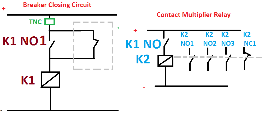
Contact multiplier relays are connected in parallel with the breaker contact. See the wiring diagram. Here k2 contactor is a contact multiplier relay. It just connected in series with the closing coil’s potential free contact. Hence whenever the K1 coil is energized K2 contactor also automatically energized, so like parallel operation.We can use these K2 contact…
TNC => It is a three way switch, T => Trip, N=> Netural, and C => Close
In industrial applications the contact multiplier comes with the 12 to 20 number of NO and NC potential free contact. if we need further contact we can extent the contact.
Key Points:
- These relay do not contribute the circuit breaker tripping or closing operation..
- They are just auxiliary types relays, we can run the power system without of them.
- The relay coil voltage may be varies according to the design… we can use any type of relay contact coil.
- It has auto reset button…but if the contact get jammed means we have to reset them manually.

 and No Voltage Relay Working Principle")


