Bus bar Differential protection or Circulating Current Protection
Bus bar Differential protection or Circulating Current Protection is working under the principle of differential protection. The current transformers are arranged as shown in the figure. Under normal condition, Incoming current in to the bus bar is equal to the outgoing current from the busbar, therefore the net circulating current is equal to zero. Since the relay become inoperative. Under abnormal condition, the fault in the protected zone, the current become unequal. Therefore, there is circulating will be present in the relay circuit. If the circulating current is higher than the pickup current the relay trips all circuit breaker.
[wp_ad_camp_1]
Note: if the fault in the outside of the protected zone, the incoming fault current is equal to outgoing current. hence the relay become inoperative.
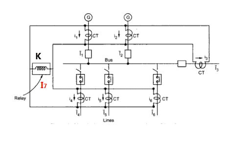
Consider Six CTs are named as CT 1, 2 ,3, 4, 5 and 6. The number 1 and 2 are the incoming CT and the remaining CTs are outgoing. K is a relay operating coil and the current flow in the CTs are I1, I2, I3, I4, I5, I6 and I7 is current flow through the relay operating coil K.
[wp_ad_camp_1]
Under Normal condition, the current flow in the relay operating coil K is equal to zero I7=0. Because of vector sum of current at node A is Zero (apply KCL). Since the relay K do not trip the circuit breaker. Consider the short circuit occurs in the bus bar, the incoming current and outgoing current become unequal. Hence the circulating current will be unequal. Therefore, there is a fault current flows in the relay operating coils. If the fault current exceeds the pickup value of the relay, which trips all the circuit breaker associated with the protection.
Notes on Bus bar Differential protection:
- To obtain exact value of circulating current, all current transformers must have exact CT ratio. But in practice there exists a difference in the magnetic conditions of iron cored current transformers and false operation of the relay is possible, at the time of external.
- CT should not be saturated under external heavy fault condition. Due to the Saturated CT, which makes the malfunctioning of the relay i.e unequal current flow in the relay operating coil even the fault is outside of the protected zone. To avoid these CT saturation trips, high impedance differential relays are used. A high resistance is connected in series with relay operating coil to get high impedance relay. This resistance is called stabilizing resistance

 and No Voltage Relay Working Principle")


