What is Zig-Zag Connection?
Zig-Zag connection is the combination star and delta connection and it has the both advantage of a star and delta.

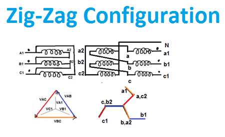
Zig-Zag configuration:
- The zigzag transformer contains six coils on three cores. The first coil on each core is connected inside out to the second coil on the next core. The second coils are then all tied together to form the neutral and the phases are connected to the primary coils. Each phase, therefore, couples with each other phase and the voltages cancel out. As such, there would be negligible current through the neutral pole and it can be connected to ground
- One coil is the outer coil and the other is the inner coil. Each coil has the same number of windings turns (Turns ratio=1:1) but they are wound in opposite directions. The coils are connected as follows:
- The outer coil of phase a1-a is connected to the inner coil of phase c2-N.
- The outer coil of phase b1-b is connected to the inner coil of phase a2-N.
- The outer coil of phase c1-c is connected to the inner coil of phase b2-N.
- The inner coils are connected together to form the neutral and our tied to ground
- The outer coils are connected to phases a1,b1,c1 of the existing delta system.
- If three currents, equal in magnitude and phase, are applied to the three terminals, the ampere-turns of the a2-N winding cancel the ampere-turns of the b1-b winding, the ampere-turns of the b2-N winding cancel the ampere turns of the c1-c winding, and the ampere-turns of the c2-N winding cancel the ampere turns of the a1-a winding. Therefore, the transformer allows the three in-phase currents to easily flow to neutral.
- If three currents, equal in magnitude but 120° out of phase with each other, are applied to the three terminals, the ampere-turns in the windings cannot cancel and the transformer restricts the current flow to the negligible level of magnetizing current. Therefore, the zigzag winding provides an easy path for in-phase currents but does not allow the flow of currents that are 120°out of phase with each other.
- Under normal system operation the outer and inner coil winding’s magnetic flux will cancel each other and only negligible current will flow in the in the neutral of the zig –zag transformer.
- During a phase to ground fault the zig-zag transformer’s coils magnetic flux are no longer equal in the faulted line. This allows zero sequence.
- If one phase, or more, faults to earth, the voltage applied to each phase of the transformer is no longer in balance; fluxes in the windings no longer oppose. (Using symmetrical components, this is Ia0 = Ib0 = Ic0.) Zero sequence (earth fault) current exists between the transformers’ neutral to the faulting phase. Hence, the purpose of a zigzag transformer is to provide a return path for earth faults on delta connected systems. With negligible current in the neutral under normal conditions, engineers typically elect to under size the transformer; a short time rating is applied. Ensure the impedance is not too low for the desired fault limiting. Impedance can be added after the secondary’s are summed (the 3Io path)
- The neutral formed by the zigzag connection is very stable. Therefore, this type of transformer, or in some cases an auto transformer, lends itself very well for establishing a neutral for an ungrounded 3 phase system.
- Many times this type of transformer or auto transformer will carry a fairly large rating, yet physically be relatively small. This particularly applies in connection with grounding applications. The reason for this small size in relation to the nameplate KVA rating is due to the fact that many types of grounding auto transformers are rated for 2 seconds. This is based on the time to operate an over current protection device such as a breaker. Zigzag transformers used to be employed to enable size reductions in drive motor systems due to the stable wave form they present. Other means are now more common, such as 6 phase star.
Application of Zig-Zag Connections:
Earthing Transformer:
It can be used as earthing transformer in a delta connected (no neutral terminal) system or an ungrounded start connected (three terminal star) where in neutral is not available for grounding. The zig zag transformer used for earthing of delta connected transformer.
In delta connected transformer there will not be path to zero sequence components and no protection can be performed for these components which increases and stress and heating in the windings. The zig zag transformer provides a neutral for the proving a path to zero sequence components during line to ground fault and allows the protection to be operated due to this fault. In the obsence of grounded neutral, voltages of healthy would increase line to line voltage level, stressing the insulation connected to equipment. Thug Zig zag transformer not only helps in protection it also reduces the voltages stress under symmetrical fault conditions.
Power Electronic converters:
In power electronic converters the zig zag transformer is used to eliminate the DC magnetizing component presented due to improper firing angles. The improper firing angles of power electronic components (SCR) may introduce DC magnetizing component and this is canceled in each limb of zig zag transformer due to opposite direction of DC magnetizing component of currents flowing in the windings on the same limb.
Earthing reference or earthing transformer
Zig zag transformer offers low impedance path to zero sequence components under fault conditions so it can be perfectly used as earthing transformer with and earthing reference. If the earthing current has to be limited under fault conditions, a suitable resistor can be placed in zig zag neutral terminal.
[wp_ad_camp_1]
Harmonic Reduction:
Harmonic voltages presented in system to some extent can be cancelled in zigzag windings due to opposite connection of winding coils.
Advantage of Zig zag transformer
- Less cost compared to Scott transformer
- Provides low impedance to zero sequence currents
- Third Harmonic suppression
- It provides perfect isolation between ground and component
- No Phase Displacement: There is no phase angle displacement between the primary and the secondary circuits with this connection; therefore, the ∆-zigzag connection can be used in the same manner as Y-Y and ∆- ∆ transformers without introducing any phase shifts in the circuits.
Ref: https://electricalnotes.wordpress.com/2012/05/04/zig-zag-connection-of-transformer/


 Chart – Transformer Wire Amperage Table")


This was a good article on Zig Zag connection. Can you provide me with articles that explain why transformer primary and secondary windings have to have a phase shift e.g. Yd1, Yd9 etc.