Short Transmission Line:
In AC/DC Power system, Transmission lines are used to transmit the power from generation station to transmitting station. Transmission lines are pair of conductor which carry electricity to the consumer’s area. These transmission lines are classified in to three categories according to the length of the transmission line. They are, Short transmission line, Medium transmission line and Long transmission line. In this, we are going to see, the entire study about short transmission line.
[wp_ad_camp_5]
Short Transmission Line Definition:
The length of the transmission line is less than 50 Mile(80kM) and the operating voltage is less than 20kV such transmission is called short transmission line. In short transmission line, the shunt capacitance offers a very small leakage current due to low voltage, since the shunt capacitance of the short transmission lines is neglected. Other transmission line parameters such as resistance and inductance are lumped (Jointly).
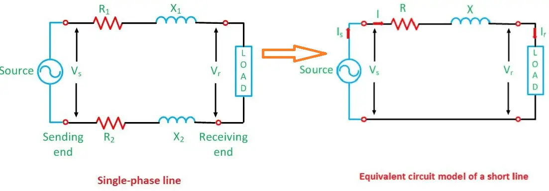
Short Transmission Line – Equivalent circuit and Phasor diagram:
The short transmission line’s equivalent circuit and phasor diagram are drawn in the figure given below. Here the lumped parameter R is considering as line resistance per phase and X is considering as line inductive reactance per phase of the entire transmission line. As said earlier the effect of shunt capacitance and conductance is not considered in the equivalent circuit. The line is shown to have two ends: sending end (designated by the subscript s) at the generator, and the receiving end (designated r) at the load. However, consider
Vr = Receiving end voltage
Vs= Sending End Voltage
Ir = Receiving end Current
Is = Sending end current
cos∅r= power factor of the load
cos∅s = power factor at the sending end
[wp_ad_camp_5]
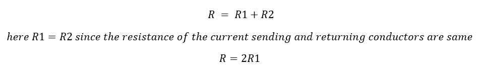
R1, R2 = Line Resistance…while considering equivalent circuit of short transmission line, the resistance R1, R2 is considered as R = loop resistance i.e., resistance of both conductors
Also the value of resistance R is
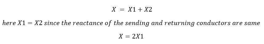
X1, X2 = Line inductive reactance…while considering equivalent circuit of short transmission line, the reactance X1, X2 is considered as X = loop reactance i.e., total reactance of both conductors
The value of the short transmission line’s inductive reactance X is
Here the series impedance is given by Z= R+jX
In short transmission line, the shunt capacitance and shunt conductance are neglected, hence sending end current and receiving end current is same, i.e.
[wp_ad_camp_5]
![]()
Lets solve,
Let’s draw the vector diagram for this equivalent circuit, Ir receiving end current as reference phasor The sending end and receiving end voltages make angle with that reference receiving end current, of φs and φr, respectively.
If nature of power factor is not mentioned therefore we have to assume it as lagging power factor ( In anticlockwise direction from reference phasor ).
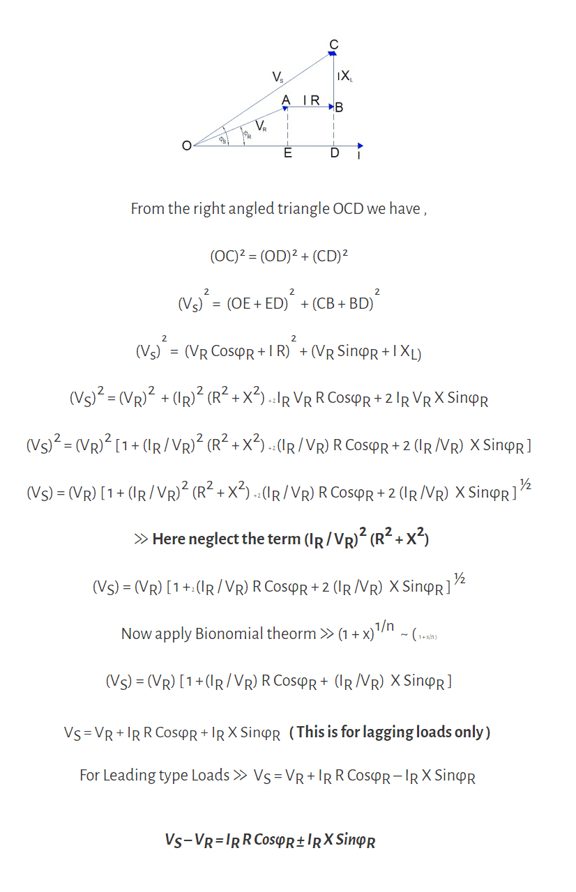
From above We get Vs is approximately equal to
![]()
Voltage Regulation of Short Transmission Line:
Voltage regulation of the transmission line is the ratio of difference between sending end voltage and receiving voltage (Vs-Vr) to receiving end voltage (Vr) is called voltage regulation of the transmission line. In short transmission line, as we said above there is no capacitance, during no load condition the current through the line is considered as zero, hence at no load condition, receiving end voltage is the same as sending end voltage. As per dentition of voltage regulation of power transmission line,
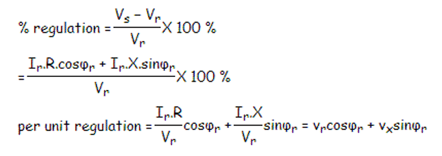
Here, vr and vx are the per unit resistance and reactance of the short transmission line respectively.
[wp_ad_camp_5]
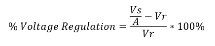
ABCD Parameter of the short transmission Line:
The ABCD constants are used to calculate the voltage regulation of the transmission line. From above voltage regulation equation Vr and Vx are the per unit values of resistance and reactance of the line. From the equivalent circuit diagram we can observe that the sending end voltage Vs and sending end current Is
Vs = Vr + Ir ( R + jX) = Vr + IrZ
Is = Ir
In a four terminal passive network, the sending end voltage and sending end current are related with the receiving end current and voltage by following pair of equations
Vs = AVr + BIr
Is = CVr + DIr
Comparing the above two sets of equations,
From that, a short transmission line gets
A = 1, B = Z, C = 0, D = 1.
ABCD constants can be used for calculation of regulation of the line as follows:
Normally the quantities P,Ir and cosΦr at the receiving end are given and of course the ABCD constants. Then determine sending end voltage using the relation
Vs = AVr + BIr
Vr(no load) at the receiving end is given by Vs/A when Ir=0
The voltage regulation:
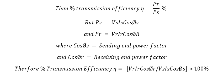
What is Transmission Efficiency?
Efficiency is nothing but a ratio between receiving end power to sending end power and the transmission efficiency is expressed in percentage. The transmission efficiency says about the transmission line how much power successfully delivered to receiving end from sending end. Let us consider, we are sending Ps MW (Mega Watts) power from sending end and the consumer receives Pr MW power at Receiving end. The efficiency of the transmission line can be expressed as
[wp_ad_camp_5]
The efficiency of the transmission line:
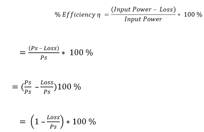
In that, You never get 100% of efficiency from short transmission line since the remaining (100 – η)% of input power consider as losses. Actually, short transmission line has its own line resistance. So, there will be an ohmic loss in the resistance of line. If Ps is the input power at sending end, then only (Ps – Loss) will be available at the receiving end. Therefore (100 -η)% is the loss in transmission line resistance. Let see the new method to calculate transmission efficiency. Here loss of the transmission line will be Loss= I2*R. Therefore, resistance of the short transmission line will be
Example for Ac short transmission lines: Local house hold electricity distribution.

 | SFTP | TFTP Full Explanation")


I read this article.I think you put lot of efforts in this article. thanks you sharing with us. electronics devices