Single Phase Induction Motor
Single-phase motor is nothing but a running a squirrel cage induction motor using a single-phase power supply. Since it has only one coil at the stator.
The magnetic field of the single-phase motor does not rotate and it creates pulses in the same and opposite direction. Due to this, the single-phase induction motor has no starting torque.
It is a handicapped version of a three-phase induction motor.
The power rating of the single-phase motor is very low. It is mainly used in domestic applications such as dewatering pumps, centrifugal fans, grinders, fans, blower etc.
Construction of single phase induction motor:
The construction of a single phase induction motor is very similar to the three phase induction motor. It has two main parts such as starter and rotor. The stator is a stationary part which carries the input voltage and current and rotor is a rotating part that delivers the mechanical output to the connected equipment.
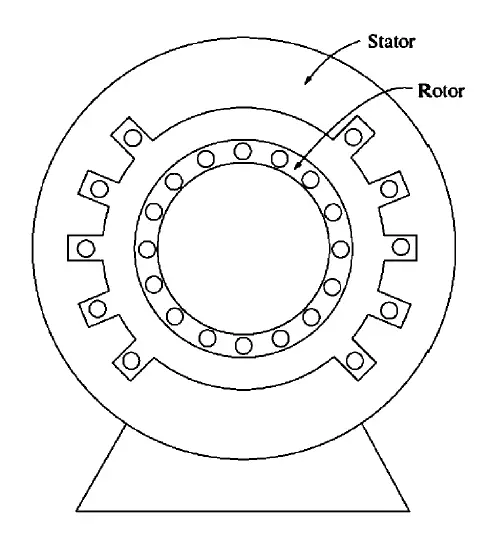
Stator
The stator is made up of silicon stamping since the silicon has a property of reducing the hysteresis losses of the motor; Also, all stampings are in laminated format for reducing the iron loss (constant losses).
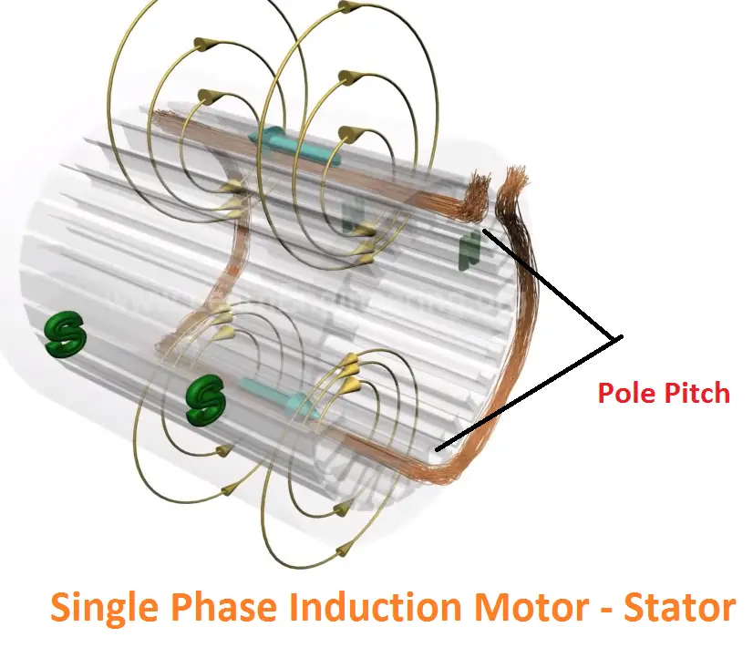
The stampings are slotted in the motor to carry the main winding of the motor (coil). In the winding part, aluminum or copper coils are used to wound the motor, but efficiency concerns mostly copper coils are preferred.
The coils are insulated in order to avoid the physical contact between the motor and the earth.
Also, there are 4 types are there such as Class A, B, F and H and they are having different temperature ranges such as 105 deg, 130 deg, 155 deg, and 180 deg.
The coils are wound in the motor to form a certain number of poles. In the construction part, the motor poles are playing a major role
The motor pole is directly proportional to the speed of the motor. The synchronous speed Ns is
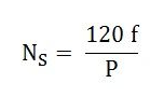
Here P => Number of Poles. It picks the synchronous speed of the motor. Remember that, motor speed never catches the synchronous speed. It always lesser than the synchronous speed.
While winding the motor, we need to calculate pole pitch of the motor. Pole pitch is nothing but a difference between 0th winding to the next winding of the same coil.
For example: Now you are winding a motor at 0th slot after completion of the 0th slot, the one end of the winding lead goes to the 9th slot. Here, the number 9 is called the pole pitch. Hence the 0th slot winding and 9th slot winding will be the same coil.
Rotor:
It is a robust construction. The rotors are made up of aluminum or copper bars. Two end side of these bars are permanently short-circuited with the help of end rings. Such construction is called a squirrel cage rotor.
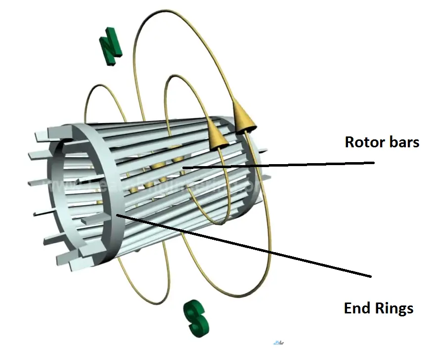
The rotor has very little resistance with high reactance.
Also, the rotor bars are filled with the silicon stampings to increase the mechanical strength as well as to increase the magnetic permeability of the rotor.
A uniform minimal distance between the rotor and starter winding is called an air gap.
Also note that the less air gap causes high torque and low speed; the High air gap causes low torque and poor power factor.
Working Principle of Single phase induction motor:
The working principle of a single phase motor is simple, it just like Thief and Police game (Police tries to catches the thief). It has two flux such as main flux which is generated by stator coil and another one is rotor flux which is produced by rotor bars. Here rotor flux tries to catch the stator. Due to this interaction, the torque is being developed.
Initially, the single phase A.C. supply is directly given to the stator winding and the stator winding generates alternating main flux. The main flux link with the rotor conductor, hence the rotor creates induced emf according to the transformer principle. Note that the rotor is short-circuited, due to this construction the induced emf causes a circulating current in the rotor conductor.
Video Explanation for Single Phase Induction motor:
As per the transformer principle, the rotor current produces another flux is called rotor flux. It starts catching the main flux, but the rotor flux and the starter flux is always in phase each other. Hence the net torque produced in the motor is zero.
However, if the motor starts to run, it continuously produces steady torque.
Double field revolving and cross-field revolving, two basic theories use to explain why single-phase induction motors are not self-starting,
Why Single Phase Induction motors are not self-starting (Double field Revolving Theory):
Let us take a full cycle of a single phase. It has one positive and another one is negative and they are equal in magnitude and different in direction. One is forward and another one in reverse.
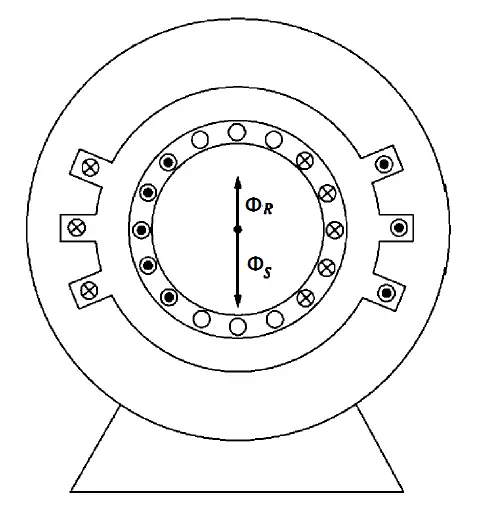
Assume that, the total flux is produced in the stator coil is Φ. During the positive half cycle, the flux is Φf/2 and negative half cycle the flux will be – Φb/2
At any instant, the sum of these two fluxes is always equal to stator flux.
Φ= (Φf/2)+( Φb/2)
Let we consider alternating current
At zero point (0, 180deg):
There is no forward or backward magnetic flux, hence the magnitude of the stator flux is zero. hence there is no torque.
A maximum point (+90deg and – 90 deg):
- At +90deg, the forward flux reaches a maximum and the rotor links the stator flux, the rotor induces emf in the forward direction and the motor start rotating at forwarding direction
- At -90deg, the reverse flux reaches the maximum and the rotor links this flux and induces emf in the reverse direction, hence the motor start rotating in the reverse direction.
Here note that the direction of the rotor flux is always in phase with the stator flux.
By referring 1 and 2 we get equal and opposite rotation for a single cycle in the motor due to the alternating nature.
The resultant torque is equal to zero and the motor rotor remains stands at the previous position.
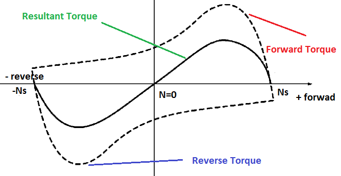
That’s why the single-phase motor is not self-starting.
Now you get a new question, then how single phase motor starts rotating while giving manual rotation at start?
We can get the answer by cross-field revolving theory.
Crossfield revolving theory:
Let us consider one cycle of single-phase,
At starting, the flux produced in both coil is zero hence, the net torque developed in the single phase motor is zero.
Now consider above 2 or 3 instant,
The resultant flux at +90 deg is Φs = Φ/2
Fortunately, you have given a small rotation to the motor shaft. Therefore, the rotor cuts the start flux dynamically. The rotor induces emf and circulates current in their conductors.
Due to high rotor reactance, the rotor current lags the rotor voltage by 90deg. Thus, the rotor current produces own magnetic flux (Φr). And Φr lags the Φs by 90 deg. Such a way that, these two fluxes produce a rotating magnetic field. The motor starts rotating.
Here the direction of the magnetic field is the same as your direction.
Types of single phase motor:
As we discussed, a single-phase induction motor does not have starting torque. Practically, each time we cannot rotate the motor manually. Hence, we need to construct self-starting motors. According to that,4 types of motor are classified such as,
- Split Phase induction motor
- Capacitor start Induction motor
- Capacitor start capacitor run induction motor
- Shaded pole motor
Split Phase induction motor:
As the name suggests, the input phase is split into two-phase with the help of auxiliary winding (A) and main winding (M). These two winding sets to 90 deg each other. The auxiliary winding has a higher resistance to reactance (X/R) ratio than the main winding. So thin wire is enough to achieve a high X/R ratio and they will not take full load current of the motor.
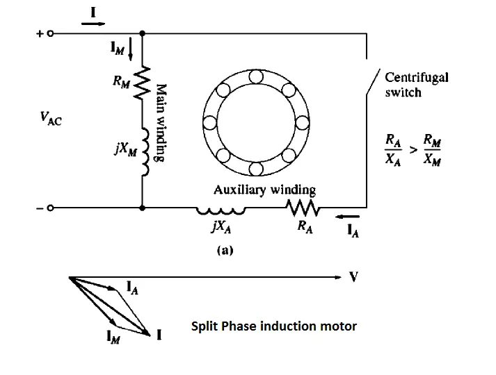
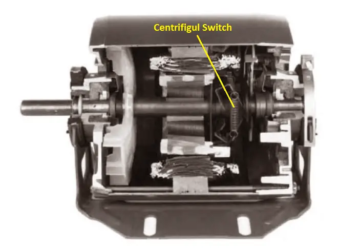
A centrifugal switch is connected in series with the Auxiliary winding; The switch has an inbuilt mechanism to disconnect the auxiliary winding from the circuit when the motor reaches 70 to 80% of the full speed.
To understand the concept of Split phase induction motor, please refer the below snaps,
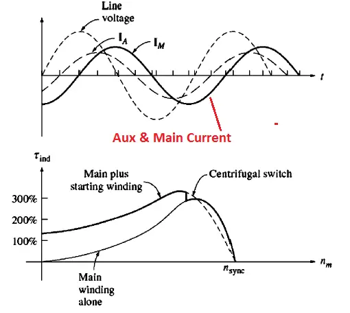
The current in the auxiliary winding Ia peaks before current in the main winding peaks. Such a way that, the magnetic field in the auxiliary winding always peaks before main winding peaks.
The direction of the magnetic field can be found by whether the space angle of the magnetic field from the auxiliary winding is 90° ahead or 90° behind the angle of the main winding.
Since the angle can be changed from 90° ahead to 90° behind just by switching the connections on the auxiliary winding.
Therefore, the direction of the motor can be changed by changing the terminal connection of the auxiliary winding without changing the terminal connection of the main winding.
Split phase motors are having moderate starting torque with low starting current, hence they are not preferable for the high starting application such as grinders, crushers, etc.
They are best suitable for fans, pumps, commercial applications
The capacitor starts motors:
The main difference between the split-phase motor and capacitor start motor is the capacitor is used to increase the starting torque of the motor.
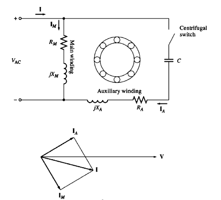
Capacitor draws leading current; this principle is used in the capacitor start motors. Hence a capacitor is connected in series with the auxiliary winding of the motor. Such an arrangement is called a capacitor start motor.
By proper selection of the capacitor, we can get an exact 90 deg phase difference between the main current and auxiliary current. Thus rotating magnetic field is generated.
When the speed of the motor reaches 80%, then the centrifugal switch disconnects the capacitor circuit automatically. The capacitor and auxiliary winding remain in the circuit under inactive condition. They are only used for starting of the motor.
Also, we can get 300% of the starting torque as compared with a split phase induction motor. They are mainly used in high starting torque applications such as compressors, air conditioners, centrifugal fans, etc. Such motors are rated up to 5HP
Capacitor start and Capacitor run motor:
Capacitor start and capacitor motors are called as permanent capacitor motors.
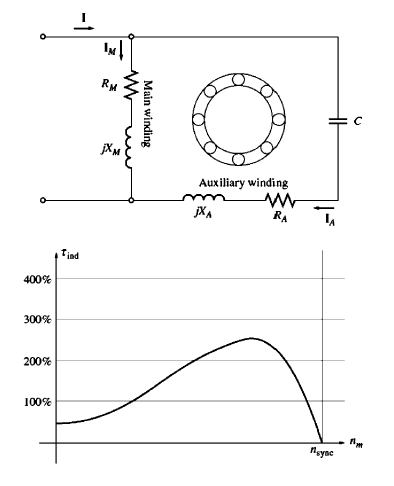
In the above two motors, we have to install a centrifugal switch inside of the motor. In case, failure of centrifugal switches, the motor will not start. To overcome such an instant, the capacitor is kept along with the motor auxiliary winding circuit. Such motors are called capacitor start and capacitor run the motor.
But Some time, to achieve high starting torque, we need a high value of the capacitor. For that, there is an another capacitor will be connected in parallel with the main capacitor. This capacitor will be disconnected after the motor reaches full speed.
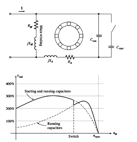
Though the starting torque of these motor is lesser than capacitor start motors, economically, capacitor start and capacitor run motor works perfectly for low starting torque application.
Here, the starting torque of the motor will be around 50-100% of the full load torque. I mean they have high efficiency and high power factor. The motors are available up to 15HP power rating.
Shaded Pole Motor:
A small single winding projected pole motor is used for small power rating application such as simple blower, hand fan circuit, exhaust fan application, etc.,

Disadvantage shaded pole motor:
- Low starting torque
- Cannot reverse the motor direction
- Poor power factor


 Construction, Working, Types, Advantages")


