INDUCTION MOTORS
In DC motors the electric power is conducted directly through commutator. Hence they are called conduction motors.
In AC motors power is received due to induction voltage. Hence the name induction motors.
Induction motors are of two types
- Three phase induction motor
- Single phase induction motor
Three phase induction motor
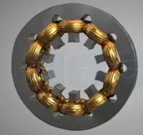
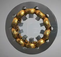
Every motor consists of two main parts stator that remains stationary. The rotor rotates continuously. The stator is the outer cylinder hallow structure it is made up of multiple laminated steel sheets join together. Many slots are provided in the inner peripheral of the stator. In which copper coil is wounded to generate the magnetic poles lower the number of magnetic poles higher the speed of motor. The actual stator is showed in figure.
Rotor
The rotor is a part of motor which acts as inner cylindrical core and rotates continuously. Once the motor is started it always kept inside the stator.
Depending upon the wingdings used the rotor is categorized
- Squirrel cage rotor
- Phase wound rotor
Squirrel cage rotor
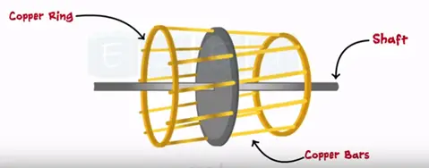
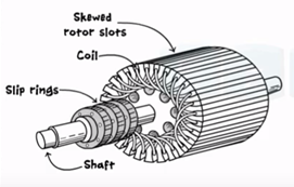
It is mounted on the center rod is called shaft. It consists of cylindrical body having multiple slots on it. The copper bars acts as a conductor mounted on these slots. Once constructed this structure looks like cage of a squirrel. Hence the name squirrel cage rotor.
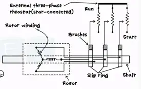
Phase wounded rotor or slip ring rotor
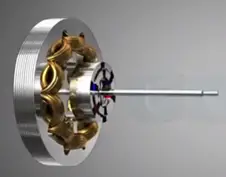
This rotor consists of a slotted laminated core or a steel mounted on a shaft copper winding is placed in the rotor slots having the same number of poles as the stator. The three brushes or slip rings connected.
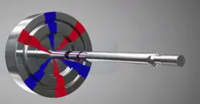
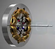
The inner equivalent structure of three phase rotor can be considering the shaft as a central axis.
Let’s see how three phase motor works
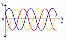
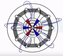
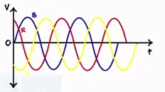
When a motor is connected to three phase supply the rotating 3 phase AC signal generates a fluctuating magnetic field across the stator. The direction of the rotation of this wheel changes according to positive and negative half AC signal.
According to faradays law when the copper bars of rotor cut this magnetic field the current gets induced in the rotor. This induced current develops own magnetic field interacts with each other. It develops a torque/force at drives the rotor in circular motion continuously. Thus three phase motor is self-starting.
If the rotor and magnetic field of the stator rotate with the same or synchronous speed motor bars will never cuts the magnetic field lines and no current induced in the rotor. Hence the rotor and magnetic field of stator never rotate with same speed.
The difference between the synchronous speed and the actual speed is called slip speed.
Slip speed = (Ns-N) rpm
% slip =S= Ns-N/Ns*100 where
Ns-synchronous speed in rpm
N-actual rotor speed in rpm
Advantage of three phase motor
Cheap, robust, reliable, can withstand overload condition
Single phase induction motor
The single phase induction motor is mainly used in fans, washing machine, mixer etc.
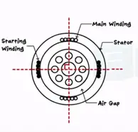
The construction of single motor is mainly used in similar to three phase motor. The stator made up of multiple sheets of laminated steel. The slots are provided inside peripheral on which coil is wounded being a single phase motor it has distributed single phase winding.
The rotor construction is squirrel cage type the copper bars are permanently shorted at both with help of end rings.
When single phase AC supply is connected to the motor the magnetic flux generated which rotates around the axis only. It never rotates like the three phase motor. Hence single phase motor is not self-starting.
To overcome these drawback auxiliary wingdings added to it temporary 90° apart from main winding and making it as two phase motor
Thus when two phase motor is supplied a single phase AC supply the rotating flux is generated. When these magnetic field lines are cut by rotor bars they conduct the current. This current induces the emf in the rotor torque is generated and drives the motor.
Centrifugal switch is connected series with the auxiliary winding and is located inside the motor. Once motor reaches the 70-80% of synchronous speed.
The starting auxiliary winding is disconnected from the supply with the help of switch.
There are three types of winding used
- Split phase motor
- Capacitor start motor
- Shaded pole induction motor
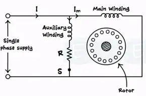
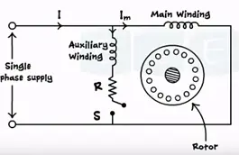
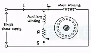
Split phase induction motor
The auxiliary winding along resistance R is placed connected across main winding. The two wingdings are 90° apart and connected parallel with AC power supply.
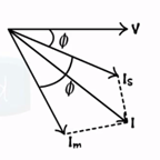
Im be the current through the main winding Is being the current through the auxiliary winding I be the motor current V is the supply voltage.
The main winding has low resistance but high reactance and auxiliary winding has low reactance and high resistance. Thus Is lags behind the applied voltage be small angle whereas Im lags the voltage V by large angle. This creates large split between two current phases and there is a split phase between the two currents. This motor is called split phase motor.
Once the motor starts the rotation it attains the considerable amount of speed. The centrifugal switch goes OFF disconnecting the auxiliary winding from the main winding motor continuous to work in main winding only.


 Construction, Working, Types, Advantages")


