How to Check Diode Working Condition?
How to test diodes
Diodes are two terminal devices and most interesting equipment in electronics. Diodes and transistor are changed world. Diodes are used to convert AC signal to DC signal. Since all the rectification action will be done with the help of diodes only. They will not failure easily in a circuit. However, when the voltage across the diode increased beyond the forward breaking voltage then the diode gets failured or damaged. So that, In this, article we are going to see how to check the diode working condition.
Before that You must know the most common reason for diode failure:
- Increase The Forward Voltage Drop,
- Severely Restrict the Dissipation of Heat from The Die. Restricted Heat Dissipation causes the Diode to Operate at Elevated Temperatures Which Could Lower Its Current Handling and/or Cause Premature Failure.
- Poor Soldering
Generally, you can check the diodes in two ways:
- Using Multi meters.
- Using Circuitry.
[wp_ad_camp_1]
How to check diodes using Digital Multi meters:
Note: Before checking any electronics or electrical equipment, make sure that was isolated from power source.
First take the diode to be tested; suppose if you have the diodes in your PCB, then if it is possible then you remove it, otherwise follow my methods to get exact result. First I explain, how to check diodes in open area.
- Take any of your multi meter
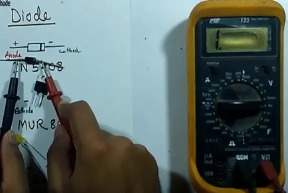
- Put it is diode mode, please refer the picture of diode mode symbol. If your multi meter does not have that mode means leave it, then put it in resistive mode.
- Connect your probe in respective terminal.
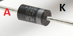
- Now you can see that the diode has two terminals, one is anode and another one is cathode. In that, you can see a white mark in one side of the diode, it is called cathode, and the opposite terminal to the cathode is called anode.
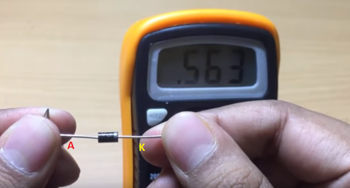
- Now you just put red color probe on your anode and block color on cathode.
- Observe the voltage value. If the value become 0.25Volts to 0.4 Volts means germanium diode and if the value is 0.55V to 0.8 Volts, then it is called silicon diode. If you get the range between both, then your diode is 99% in good condition.
- Also one more point, Now just reverse the polarity of the multimeter. If you get the Value as infinity “OL” open means, then your diode is 100% good, you can put them on work.
Note: i.e if you get the value of 0.02V (less than 0.25V) or OPEN on Both Side, Which means, your diode has failured.
[wp_ad_camp_2]
Watch This Video In English How to Check Diodes:
How to check the diodes on PCB board itself?
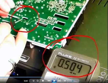
PCB is a short term of printed circuit board. PCB are generally insulated using varnish, epoxy, pcb resin etc. So that before checking any electronics components, just clean their terminal with sharps.
In PCB, clean the terminal of the diode, now follow above procedure carefully, Do not touch any integrated circuit, which may get failured due to our body static voltage.
If you want more accurate result, then remove one of the terminal of the diode from PCB and continue above procedure.
Note: If you are planning to check the diode in PCB itself means, do not use analog multimeters, use digital multimeter which should have diode mode option.
[wp_ad_camp_3]
How to check the diodes using Analog multi meter:
In analog multi meter, you cannot get the integer values and it may not have diode option. So that follow my steps to check the diodes using analog multi meter.
- Take an analog multi meter
- Put it in ohm position
- Connect the multi meter positive and negative probe with diode’s anode and cathode.
- If you get the value between 100 ohms to 1K ohm or it should give the parallel resistor value, when connecting positive to anode and negative to cathode means your diode is good for 80%
- Now reverse the polarity, they if you her the value of infinity (open), then your diode is 100% ok. You can put in work.
2. Circuitry way to check the diodes:
Using This method, you can confirm, the diode working stats for 100%. Connected your diode in series with the LED lamp through a 5 Volts AC source. Now switch on the power.
If our Diode is good, then our LED bulb starts glows, If not, then our diode can not be used.
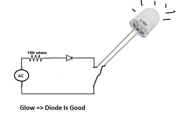
Note: Before conducting this circuit make sure, your power source and LED is in Working Condition.


nice but how to know the resistance of diode?this post is about http://ceneloctronics.blogspot.com/2018/07/basic-diode-in-hindi.html