T-Pad Attenuator Calculator
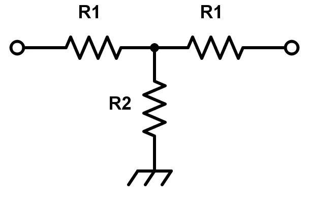
The name T comes because the topology of electronic circuit is in shape of T. when the signal or power is high circuit it results in damage of circuit or improper results to avoid T type attenuator is used to reduce the signal or power to desired level. Attenuator is directly opposite to amplifier. Attenuators have ability to work all frequencies equally. Attenuator circuit is a simple circuit that acts like a filter sections so there is no need of complex circuit.
Depending upon transmission lines circuit to be balanced or unbalanced circuits. Radio frequency applications unbalanced circuits are required as coaxial but for communication applications the balanced circuits are needed as twisted cables.
T is basically unbalance circuit but it can be able to change as the balanced circuit by connecting the resistance as a series in return path. Radio frequency are most commonly used this attenuator. Construction of this topology is very simple compared to other topologies.
Formula
R1=Z[10AdB/20−1/10AdB/20+1]
R2=2Z[10AdB/20/10AdB/10−1]
Where
R1 = T pad attenuator resistor 1
R2 = T pad attenuator resistor 2
Z0 = Transmission line characteristic impedance
AdB = Desired attenuation in dB
Example
Let’s calculate resistance R1 and R2 by using T pad Attenuator. consider Attenuation (AdB) = 20, Impedance(Z) = 25.
Let’s apply formula R1
R1= 25[1020/20-1/1020/20 +1]
R1 = 20.45 Ω
Let’s apply formula R2
R2 = 2*25[1020/20 / 1020/10 -1]
R2 = 5.051 Ω