Intro about Contactor
A contactor is an essential part that is used to control the various equipment’s electrical/electronic circuits. for example, starting of an induction motor, the starter is built with the contactors only and it works as a power managing tool.
Apart from the motors, they are used in lighting circuits, electronics complex device control, automation electric vehicles, transformers, heaters, etc.
What is Contactor?
Definition: Contactors are nothing but electrically operated switching devices that work based on Faraday’s electromagnetic induction principle. The primary operation of that is much like a relay, but they are manufactured to carry high current typically up to 12500A.
Contactor Denotation:
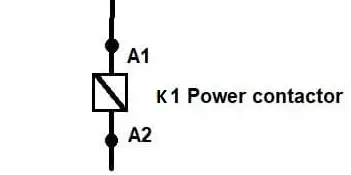
A contactor is denoted by an English letter “K” and the coil is indicated by A1 and A2.
The main disadvantage of the contactor is that they won’t protect the circuit from any other faults such as over current, overload, earth fault, and short circuit.
They have high wear & tear factor. Therefore, the different duties of the contactors are generally preferred.
Construction of a Contactor
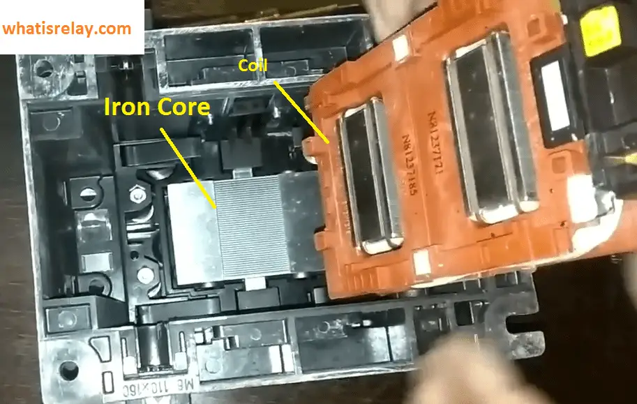
Contactors are consisting of six major parts such as iron cores, an electromagnetic coil, Arc chute, Contact tips (Fixed and Moving Tips), mounting mechanism and contactor body.
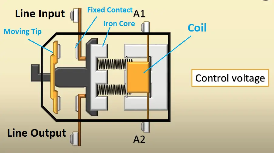
A movable iron core is placed inside of the copper wound electromagnetic coil whose input terminal will be connected to the power supply.
Six number of contact tips are consisting of three number of the fixed contact and three number of moving contacts, wherein three are fixed contact is mounted in the body of the contactor as shown in the figure.
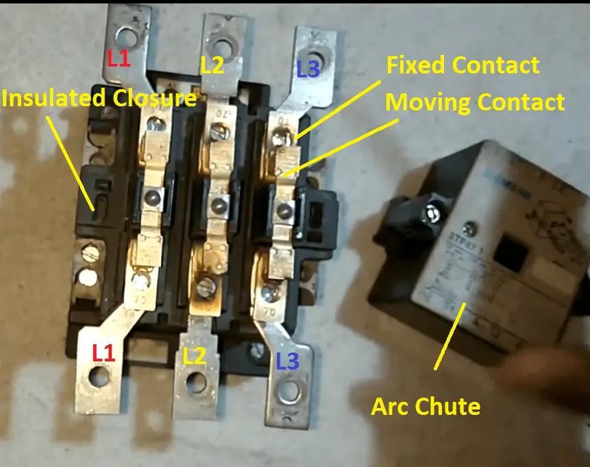
And three moving contact tips are mounted with the contactor’s iron core and they move along with the iron core.
Contact tips are made of natural copper with a smooth surface to ensure accurate contact between fixed and moving tips. And the contact points are coated with silver alloy to withstand excessive arcing temperature.
An Arc chute is used to quenching the electric arc being developed during the contactor opening. It is made of zircon-filled phospho-asbestos material.
The contactors are being constructed along with the parasite element of NO & NC auxiliary contacts which are used to control the circuits.
Contactor body/enclosure:
It is made up of different materials like Nylon 6, Bakelite, Thermosetting plastic, etc., An enclosure is used to guard the coil and contactor. Also, it is used to protect the contactors from external physical touch, dust, human contact, etc.
The mounting mechanism is just quite an interesting one, it has two screws both are locked in the contactor enclosure. It is used to connect the enclosure, contactor, and arc chute.
For a higher rating contactor, the arc chute can be removed By pushing those two screws. But smaller rating contactor we cannot easily remove the arc chute from the contactor.
Working Principle of Contactors
At the time of starting the electromagnetic coil is energized by the input and it will create an electromagnetic field. Hence the coil attracts the iron core.
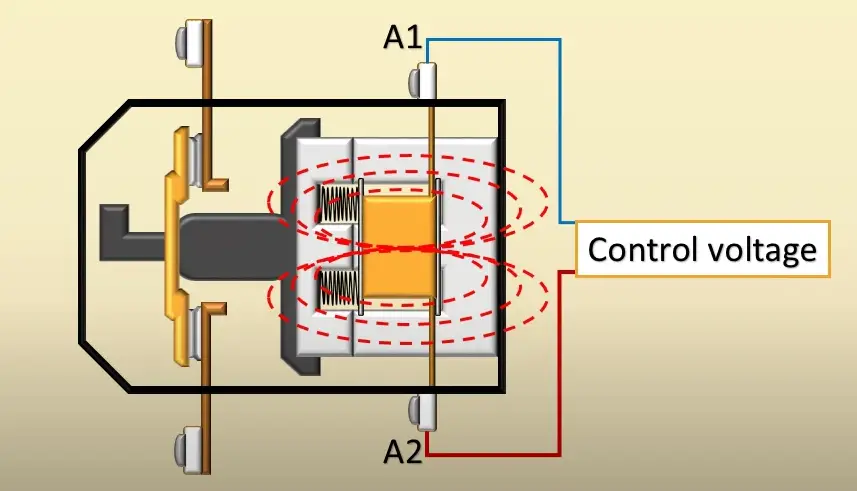
Due to the attraction of iron core, the moving contact associated with the iron core is pushed forward, as a result, the pressure created by means of the electromagnet holds the moving and fixed contacts together. Also, the releasing spring will be charged along with the iron core.
Once if you de-energize the contactor coil, the spring moves the iron core to its initial position
Contactors Operation:
The contractor is having four (for single-phase supply) or six terminals (three-phase supply). They are indicated as shown in fig 1.1.
For example, you take three-phase contactor with the small motor and contactor terminals L1, L2, L3 is the input side and L4, L5, L6 are the output side. look at the table for better understanding,
| Phase | Input | Output | Transfer Connection sequence |
| R | L1 | L4 | While connecting L1 and L4, R phase will transfer |
| Y | L2 | L5 | While connecting L2 and L5, Y phase will transfer |
| B | L3 | L6 | While connecting L3 and L6, B phase will transfer |
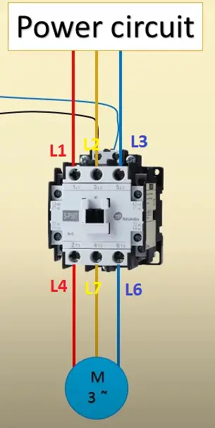
During the de-energized condition, all terminals will be in open condition, hence there is no current flow and the motor will not rotate.
While energizing the coil, the coil holds the contacts. Hence the input L1 & L4, L2&L5 and L3 & L6 will be connected through the moving contact. Finally, the motor starts rolling.
When you de-energize the coil, the spring association push the moving contact lower back to its initial position and energy supply to the motor is cut off.
Advantages & Disadvantages
The following are the advantages to be highlighted for the contactor
- High-speed switching suitable for high breaking current
- The high degree of safety can be maintained
- Cheaper than circuit breakers
- Available for different ratings
- Maintenance Free
- In modern days, the contactor comes along with the protective relays.
Disadvantages of Contactor:
- The coil needs an external power supply.
- Wear and tear factor is high
- AC and DC coils need to be manufactured, there are no universally operated coils. Hence AC coil can not be used instead of DC coil.
- Contactor Tips will be damaged easily. Hence it will be landed with the high maintenance cost
Applications of Contactors
- Induction motor starters
- Control logic circuits
- Vacuum contactor
Extremely useful information
Thanks a lot from my heart.
Finally….a clear explanation of how a contactor actually works. Well done, and thanks!