Why does VFD DOL changeover circuit require:
VFD DOL changeover circuit: Due to some reason the starter or vfd of the induction motor got failured means we need an alternative arrangement immediately or We need a good back up in order to avoid breakdown or stoppage in an industry. Here we are going to discuss about the circuit diagram of VFD to dol or dol to vfd change over drawing. Using This scheme you can run the induction motor with either VFD or DOL. The circuit works as exact alternate for both starting method of the induction motor.
When we have to use VFD DOL changeover circuit?
-
- Permanent failure on vfd or dol starters
- Temporary failure on vfd, like software error, cable burning, connector issues, etc
- Emergency pumps Ex: Condensate water pump, Boiler DM (demineralized) water pump, firefighting Jacky pump and all emergency pumps.
- When motor trial Require.
VFD DOL changeover circuit diagram:
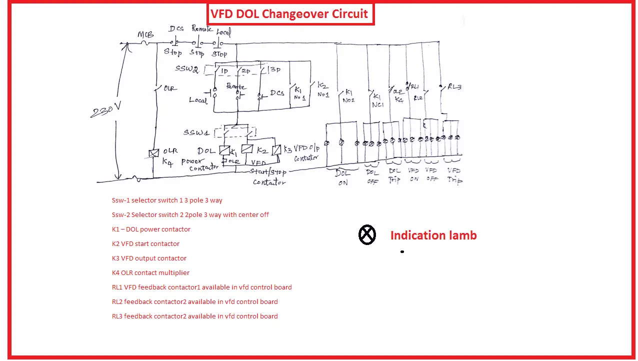
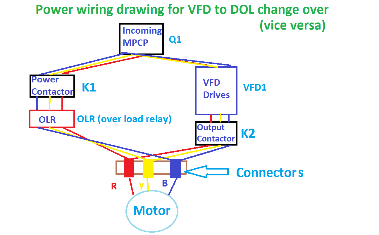
Materials Required for Power circuit: as per your capacity or range
Power circuit:
Required Materials to build VFD DOL changeover circuit:
Power contactors: 2
[wp_ad_camp_3]
Thermal Over Load Relay :1
Power cable as per your size.
VFD: as per your amperes of KVA rating
Connectors:3
Connector mounting C channel: 1 meter
Push button: 2 (Stop=1/start=1)
Push Button NO (Normally Open): 1
Push button NC (Normally Close): 1
Indication lamb: 3 reds, 2 yellow, 2 green,
MCB 2 pole, 2 Amps: 1
Note: While selecting of MCCB Just purchase the protection of short circuit and over current protection is enough to this application. Earth fault protection is not necessary.
Control contactor: 1
Note: While selecting contactor, make sure its coil voltage range (230V), Frequency (50) and which type of power supply required.
Cable 4 sqmm multi stand flexible copper cable: 5 meter each colour R, Y, B
Cable 1.5 Sqmm multi stand Flexible Copper cable: Required
Connector: Required
Connector mounting C channel: 1 full length
Control NO: 2, Control NC: 2
Starter control panel: 1 Size minimum LXDXH (400X450X400)
Note: All the above materials are example for the explanation purpose only, their range and quantity can be changed as per our load requirement
How VFD DOL changeover circuit works:
Whenever vfd has got failured means you can start your motor using DOL starter without delaying. you can perform this action by selector switch or DCS or power selector switch. DCS control works from computer’s software like Honeywell or Siemens or ABB etc. DCS method is the most effective method as compared with other method. It does not require any mechanical action and very fast. But only one drawback is you should check the feeder before making change over. Any abnormal condition leads to flash over in inside the feeder.
[wp_ad_camp_3]
Here we have three start/stop, speed increment/decrement option in vfd like Local, Remote and DCS. But in DOL we cannot change motor speed it runs at constant speed but we can make start/stop through local remote and DCS.
Let see the working combination:
| ssw1/ssw2 | Local | Remote | DCS | Ok => Circuit Works |
| VFD | ok | ok | ok | |
| DOL | ok | ok | ok |
Ex: When You select VFD + Local => Vfd starts from local or panel control pushbutton likewise all the remaining circuit works.
Also see:
- VFD Start Stop Through DCS Remote Local
- VFD start stop wiring diagram
- Why Inductors Use In Filtering Circuit and VFDs
- Why line chokes are used in VFD
- Why VFD Duty Motor Frame Size is Higher Than Normal Motor
- Why in India 11kV, 22kV, 33kV, 66kV, 132kV…
- Why India has 50 Hz Power System and US has 60 Hz 110 Volts Power System
- Why PT and CT Terminals are Star Connected
- Why PT burden is high Compare with CT burden?
- Why Star delta starters are preferred for higher HP motor
- Why induction motor Takes high starting current
- How to avoid star delta Timer failure in star delta starter
- Star Delta starter wiring diagram with Full Explanation
- What is Star Connection in Three Phase Power System


Sir please explain the programming in VFD