Thermal Over Load Relay vs CT operated thermal overload Relay:
Thermal over relay:
Thermal overload relay is simple over current protection, it does not protect from single phasing or phase failure, short circuit, and earth fault. The operating principle of the relay is, when current flow through a conductor increases then I^2 X R loss also increases (Heat loss or ohmic loss). Heating element (bimetallic strip) will be placed inside of the relay unit. Here the thermal energy is converted into mechanical energy and was associated with the bimetallic strip. Bimetallic strip operates the tripping mechanism.
The tripping unit controls the NO/NC associated with that control circuits. The control circuit operates the power circuit to be tripped. It will happen only when the excessive current flow than the pre-set current value in the thermal overload relay.
In this type of relays are directly connected with the power circuit and direct full load current passes through it. You can set your current limit through the current limiter as shown in the figure.
These types of relays are mainly used for low voltage and low load current applications (below the Full load current 200 Amps, < 110 KW). If your load current is more than 200 Amps better go for CT (current transformer) operated relays which gives better performance than this type relays.
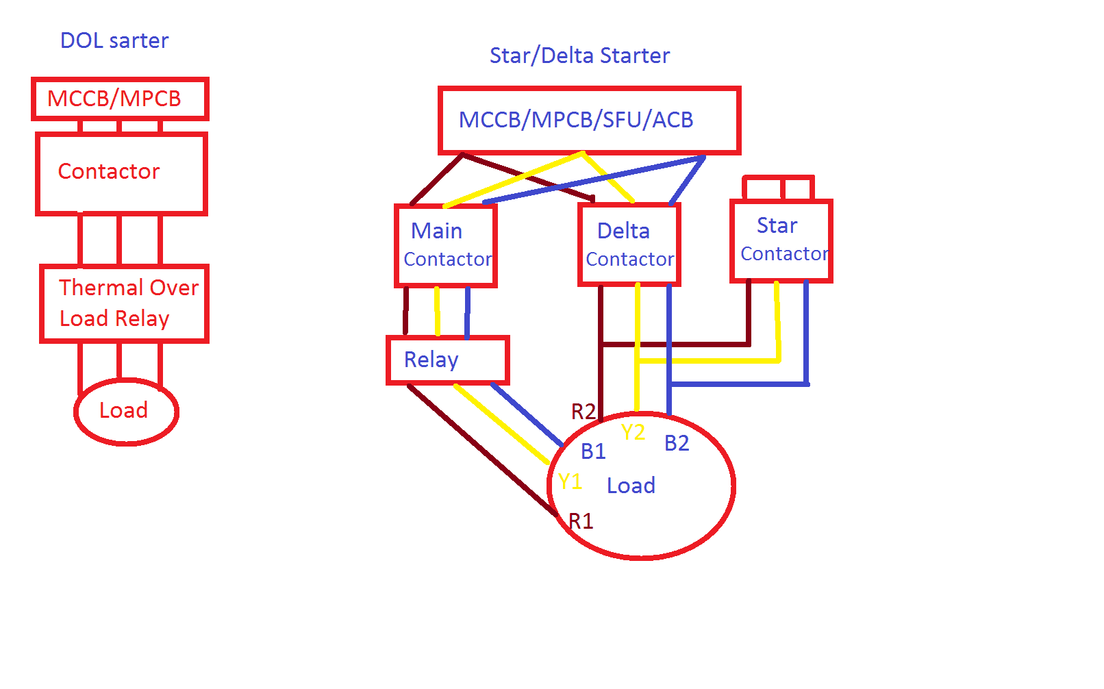
You can use this for DOL, Star-Delta starter, Autotransformer starter in AC motor/load application and all DC motor starter applications.

How to calculate relay range for DOL starter:
- Calculate the full load current of your load setup.
- Take 150% relay range
For example, your load current is 32 A (18.5 KW) choose the relay range between 27 A to 44 amps, set a current limit as 30 A.
Calculation for Star/Delta starter:
- Calculate FLA (Full Load Amps)
- As per the star/ delta thumb rule Phase current = Line current/ 1.732, during delta mode the relay range = FLA/1.732.
Also see: Relationship between line and phase current & voltage in star/delta
Ex: Your FLA = 143 Amps (75 KW, 3 Phase, 415 Volts), then the relay range = 143/1.732 = 82 Amps. You have to select 75 – 100 Amps relay.
The factor of Consideration while selecting a thermal overload relay:
- Select appropriate relay for the appropriate contactor.
Ex: If you have Siemens 3TF 33 model contractor, then you have to purchase for suitable relay for that conductor. Different model relays are coming for the different model contactor.
-
- Relay mounting kit
In Some cases, (upgrading starter panel) we have to purchase it additionally.
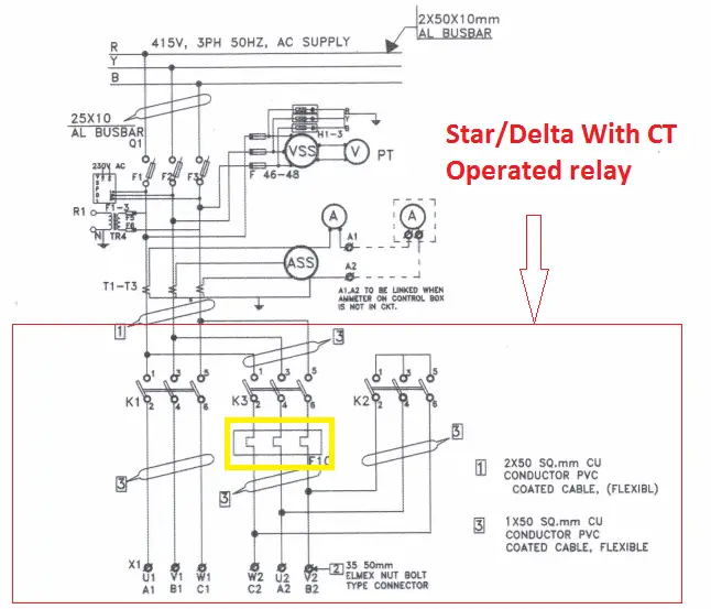
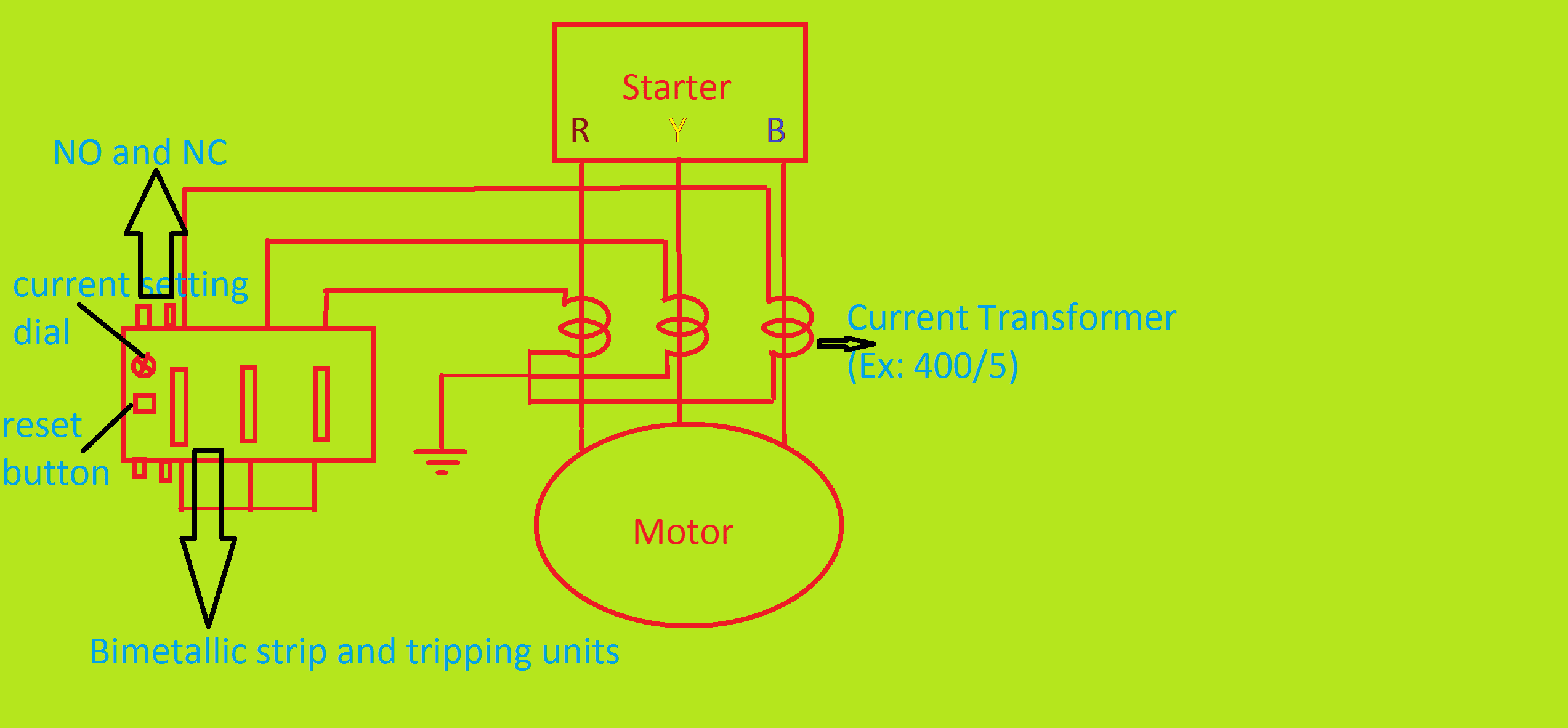
CT operated thermal overload relay:
For more than 150 HP (FLA= 200 Amps) motor these kind relays give better performance than normal thermal overload relays. Three numbers of CTs (current transformer) place at the output terminal of the starter. The output current of the CT directly connects through a small range of thermal overload relay. The range of thermal overload relay will be 0.45 to 1 Amps or 1.5 to 5 Amps, because of the standard size of CT output is 1 amp or 5 amps. Two types of connection, you can make with the CTs
- Direct connection:
Output of the CTs directly connects with relay as shown in figure.
- Star connection:
Output of the current transformer connects in star mode
How to set current limit for CT operated thermal overload relays:
Calculate motor’s FLA
Ex: A siemens Make motor 415 V, 3 PH, 220 KW, 0.8 Power factor, FLA = 400 Amps
DOL Starter:
In starter’s CT ratio = 500 / 5, Relay range = 1.5 Amps to 5 amps, which means if your line current is 500 Amps then CT output will be 5 amps
then the Line current is 400 Amps, CT output will be 4 Amps, In relay, you have to set it for 4 amps for 100 % Load (Full load)
For 90 % of Load (360 Amps), CT output will be 3.6 Amps, then you have to set 3.6 Amps in the relay and so on.
The current setting for the star/delta starter:
Consider CTs are placed at the output of the contactor, In this phase current will come to action, you have to calculate phase current of the same. Take the same motor data. FLA = 400 Amps, Same CT 500/5 Amps
Phase current = 400/1.732 = 231 Amps
CT output for 100 % Load will be = 2.31 Amps. You have set the current limit as 2.3A in relay
For 90 % of load CT output will be = 2.1 Amps, Set 2.1 amps as current limit in relay.
Note : The CT operated thermal over load relay operates according to the the load current setting in the relay. If you want to limit at 70% the load to the motor, calculate the current and set the limit it in the relay
IF the CTs are placed at the output of the MCCB/MPCB (contactor input) you have to take above mentioned DOL Calculation…
Also see:
- Standby Earth Fault Relay Operation 51N
- Restricted Earth fault Protection 64R
- What is MCC & PCC Panels
- What is Busbar & How to calculate current carrying capacity
- Relay Codes for all Relay From 1 to 150 Numbers
Thanking You!!! Have a Nice day….


 and No Voltage Relay Working Principle")


THANKS FOR THIS VALUABLE INFORMATION.
BEST REGADS
Salem Khanfasi