Single Phase Preventer Working Principle:
Single phase preventer is used to protect the induction motor from single phasing fault. Single phasing is a very dangerous fault to the electrical motor and Which damages the motor stator winding rapidly.
Generally single phasing is nothing but a motor runs when one of the supply is disconnected due to open circuit or improper contact in switch or other electrical equipment failure.
Normally, the motor runs with the three phase supply and which takes balance current in each phase winding. Consider one of the fuse has blown. But the motor still in a rotating position which tries to rotates at the same speed.
At that same time, the absence phase current will be shifted to the remaining live phases. Therefore, the current in the other phases increases up to 3 times its normal value instantly. This is called a single phasing fault.
The single phasing leads to an unbalanced current in the motor stator. The component which is present in this unbalanced current called negative sequence component.
This negative sequence component creates the magnetic flux opposite to the main flux. This results in double frequency currents to induce in the rotor to cause its heating.
Current sensing Single Phase Preventer:
Current sensing single phase preventer works like a negative sequence relay. It gives protection up to motor terminals. It operates on the principle of sensing negative sequence components of the system. Different types of relay manufacturers give additional functions such as reverse phasing, unbalance supply and under voltage /over voltage trip with that single phase preventer.
Voltage sensing single phase preventer:
The relay senses the negative sequence components of voltage in the motor power supply.
Single Phasing Preventer Working Principle:
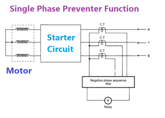
The three-number of current transformer is placed in each phase of the power supply. The output of the current transformer is given to the negative sequence filter circuit and which senses the magnitude of unbalance.
The filter circuit will be connected to the control circuit. The control circuit sends the trip command to the circuit breaker if the negative sequence current exceeds the preset value. If the failure of single-phase the unbalance current flow in the motor and the current will be sensed by the negative sequence filter.
Then the control unit sends the trip command to the circuit breaker or other motor isolating mechanism.
Also see:
- Phase Fault Protection | Induction Motor Protection
- Resistance split-phase motor induction motor
- Torque Equation of Three Phase Induction Motor
- What is skewing of an induction motor?
- What is Slip of the Induction motor
- What is Slip ring induction motor Practical explanation and Pictured
- 88 Number of Generator Protection
- Why induction motor Takes high starting current
- Why Star delta starters are preferred for higher HP motor
- CT Operated Thermal Over Load Relay Current setting Calculation
- How to Understand Motor Nameplate Details-ND 280 M/S/L

 and No Voltage Relay Working Principle")


