PLC DCS Start Stop Wiring diagram:
Start means you are going to start the electrical apparatus and stop means you are going to stop the electrical apparatus. Let see the simple start stop wiring diagram. We can perform start stop wiring by two ways. One is inches start/stop method, and another one is Continuous start/stop method. These two method of starting mainly used in PLC and DCS.
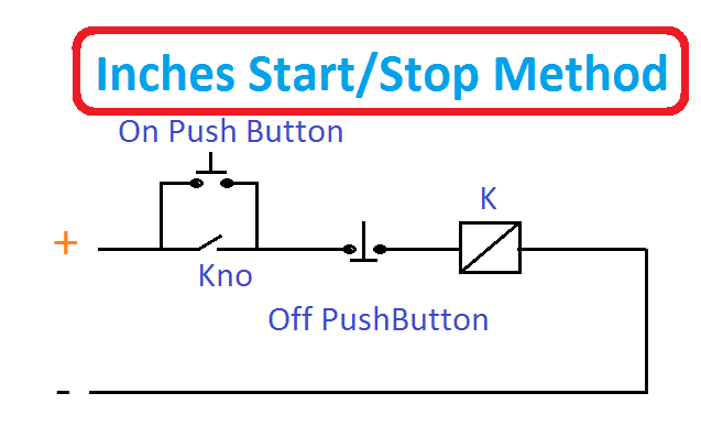
Inches start/stop method:
In this, we have to give one pulse (single command) to start the contactor afterward we can return it back or disable the pulse, the circuit start working. To stop the same, we have to give pulse to the NC associated with relay unit. Refer the diagram, where the on & off push button work as start stop control of the circuit and Kno ensures the continues working.
[wp_ad_camp_1]
Example: DOL Starters, Star/Delta Starter, VFD
Continuous pulse method:
In this, we have to give continues command or pulse to start the contactor. If the command is unavailable, then the contactor become in operate.
[wp_ad_camp_1]
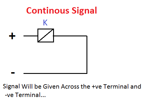
Example: PLC start, DCS control circuits.

 and No Voltage Relay Working Principle")


Full wiring diagram of plc with pdf with example